


7
1. Introduction
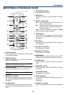
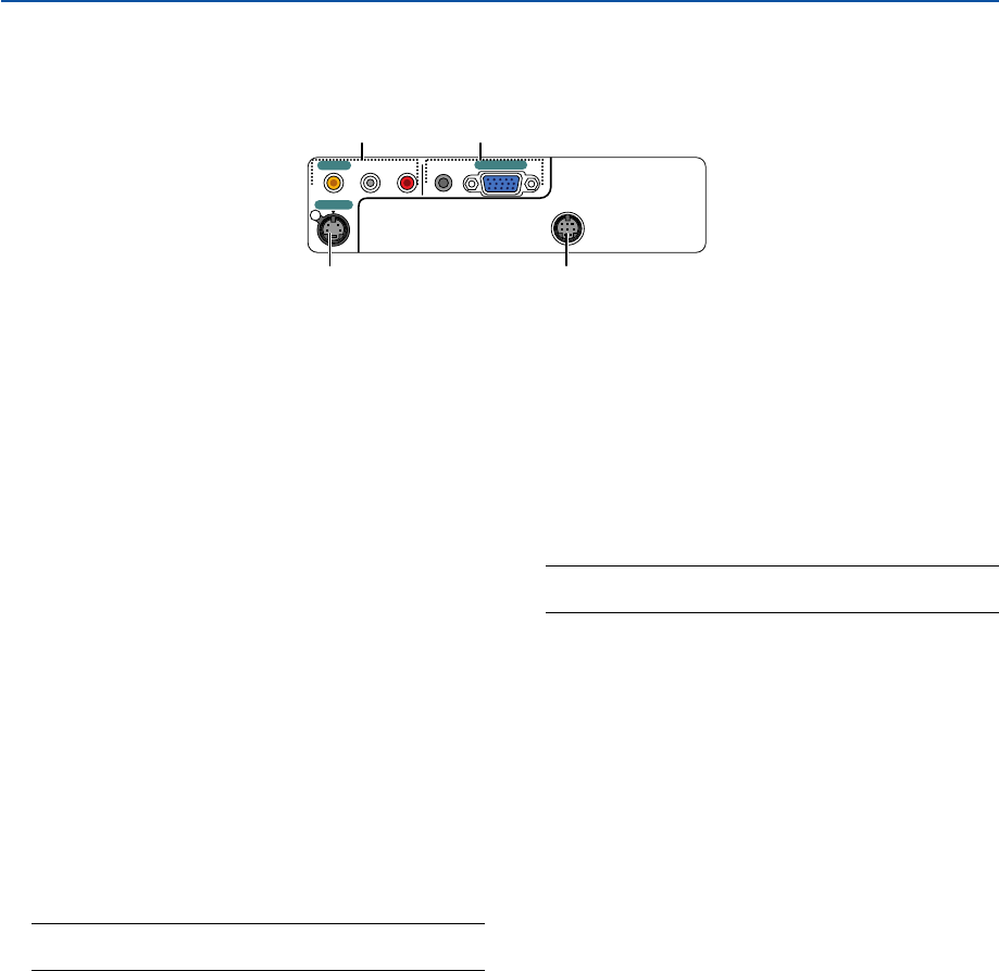
AUDIO
S-VIDEO IN
VIDEO IN
COMPUTER IN
PC CONTROL
L/MONO
R
AUDIO
3 1
2 4
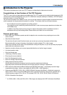
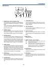
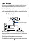
Ter minal Panel Features
1. COMPUTER IN / Component Input Connector (Mini
D-Sub 15 Pin)
Connect your computer or other analog RGB equip-
ment such as IBM compatible or Macintosh comput-
ers. Use the supplied RGB cable to connect to your
computer. This also serves as a component input con-
nector that allows you to connect a component video
output of component equipment such as a DVD player.
This connector also supports SCART output signal.
See page 15 for more details.
COMPUTER AUDIO Input Mini Jack (Stereo Mini)
This is where you connect the audio output from your
computer or DVD player when connected to the COM-
PUTER input. A commercially available audio cable is
required.
2. S-VIDEO IN Connector (Mini DIN 4 Pin)
Here is where you connect the S-Video input from an
external source like a VCR.
NOTE: S-Video provides more vivid color and higher
resolution than the traditional composite video format.
3. VIDEO IN Connector (RCA)
Connect a VCR, DVD player, laser disc player, or docu-
ment camera here to project video.
VIDEO AUDIO Input Jacks L/R (RCA)
These are your left and right channel audio inputs for
stereo sound from a Video source.
NOTE: The VIDEO AUDIO inputs can also be used as S-
VIDEO AUDIO inputs.
4. PC CONTROL Port (DIN 8 Pin)
Use this port to connect a PC or control system. This
enables you to control the projector using serial com-
munication protocol. If you are writing your own pro-
gram, typical PC control codes are on page 57.