


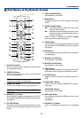


12
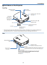
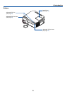
2. Installation and Connections
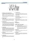
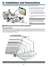
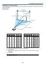
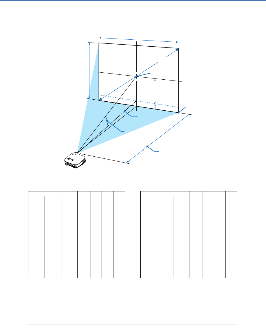
Lens Center
Throw Angle (Ͱ)
Throw Distance (C)
Screen center
Screen Diagonal
Screen Width
Screen Height
Screen Bottom
(B)
(D)
A
C
I
N
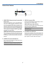
Throw Distance and Screen Size
The following shows the proper relative positions of the projector and screen. Refer to the table to determine the
position of installation.
Distance Chart
B = Vertical distance between lens center and screen center
C = Throw distance
D = Vertical distance between lens center and bottom of screen (top of screen for ceiling
application)
α = Throw angle
NOTE: Distances may vary +/-5%.
α
inch
15
18
24
36
43
48
50
54
60
72
90
108
120
126
144
162
180
Screen Size
BD
Diagonal Width Height
inch
-2
-2
-2
-4
-4
-5
-5
-6
-6
-7
-9
-11
-12
-13
-15
-17
-18
inch
6
7
10
14
17
19
20
22
24
29
36
43
48
50
57
65
72
inch
25
30
40
60
72
80
84
90
100
120
150
180
200
210
240
270
300
inch
20
24
32
48
58
64
67
72
80
96
120
144
160
168
192
216
240
C
inch
23
28
37
56
68
76
80
85
95
114
143
172
191
201
229
258
287
degree
14.6
14.5
14.4
14.2
14.2
14.2
14.2
14.1
14.1
14.1
14.1
14.1
14.0
14.0
14.0
14.0
14.0
α
mm
381
457
610
914
1097
1219
1280
1372
1524
1829
2286
2743
3048
3200
3658
4115
4572
Screen Size
BD
Diagonal Width Height
mm
-40
-50
-60
-90
-110
-120
-130
-140
-160
-190
-230
-280
-310
-330
-370
-420
-470
mm
150
180
240
360
440
490
510
550
610
730
910
1090
1210
1270
1460
1640
1820
mm
635
762
1016
1524
1829
2032
2134
2286
2540
3048
3810
4572
5080
5334
6096
6858
7620
mm
508
610
813
1219
1463
1626
1707
1829
2032
2438
3048
3658
4064
4267
4877
5486
6096
C
mm
580
700
950
1440
1730
1920
2020
2170
2410
2900
3630
4360
4850
5100
5830
6560
7290
degree
14.6
14.5
14.4
14.2
14.2
14.2
14.2
14.1
14.1
14.1
14.1
14.1
14.0
14.0
14.0
14.0
14.0