


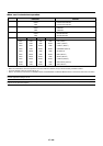
E – 18
OUTPUT
INPUT3
OPTION
REMOTE1
RGB
OUT
IN
REMOTE2
REMOTE3
INPUT7
INPUT8
INPUT5 INPUT6
OUT
LED
ON
OFF
IN
IN
Y
C
S-VIDEO1
S-VIDEO2
VIDEO1 VIDEO2
R/Cr
B/Cb
Cb
H/HV
VV
H/HV
B/Cb
G/Y G/Y
R/Cr Cr
SDI
Y
INPUT2 INPUT1 INPUT4
OUTPUT
INPUT0
RGB DIGITAL
INPUT9
OUT
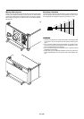
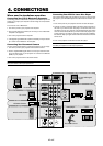
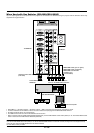
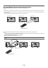
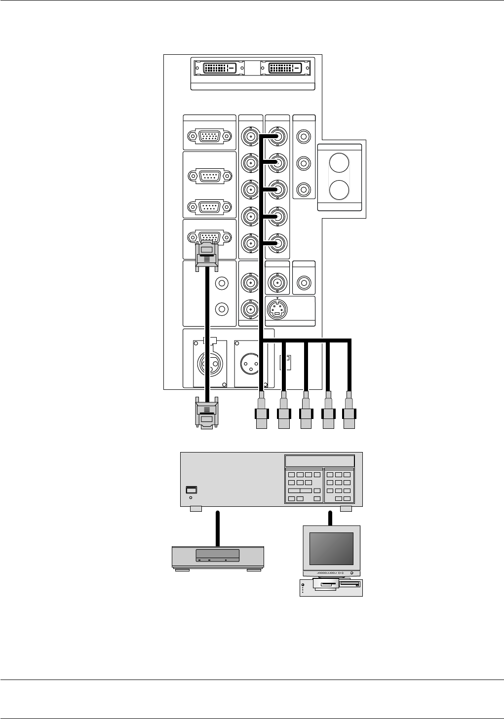
When Used with One Switcher (ISS-6020/ISS-6020G)
Up to 10 input signals can be accepted when the projector is connected to one Switcher. Using the projector with the Switcher allows easy
adjustment and signal selection.
• Select [Menu] → [Projector Options] → [Switcher Control] → [SW1 Level]. See page E-39 for the information in detail.
• For more information on the Switcher, refer to the user's manual accompanying the ISS-6020/ISS-6020G Switcher.
• All cables mentioned above are sold separately.
• The RGB2 terminal will not work with the Switcher Control function.
* When connecting with the VIDEO INPUT MODULE (6020-VID), set the VIDEO MODE select switch (S3001) to "8". The VIDEO MODE select
switch is located on the VIDEO INPUT MODULE (6020-VID).
NOTE: While in the Switcher Control mode, a video standard is selected at the projector.
If you set the VIDEO MODE select switch (S3001) to "8" with the QUAD DECODER installed in the Switcher ISS-6020, the image will not be displayed correctly.
In that case, first remove the QUAD DECODER from the Switcher ISS-6020.
For more details, contact your dealer.
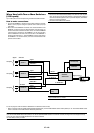
The Switcher
ISS-6020/ISS-6020G
Personal computer
VCR
From R, G, B, H/V on separate H
and V. on the RGB OUTPUT module
To REMOTE1
To SYSTEM CONTROL
REMOTE 1
Optional control cable 15p-15p
(CTL-6010)
To INPUT 1
3BNC-3BNC cable (sync on green)
4BNC-4BNC cable (composite)
5BNC-5BNC coaxial cable
(separate sync)
(recommended)