


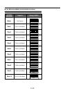
E – 24
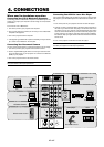
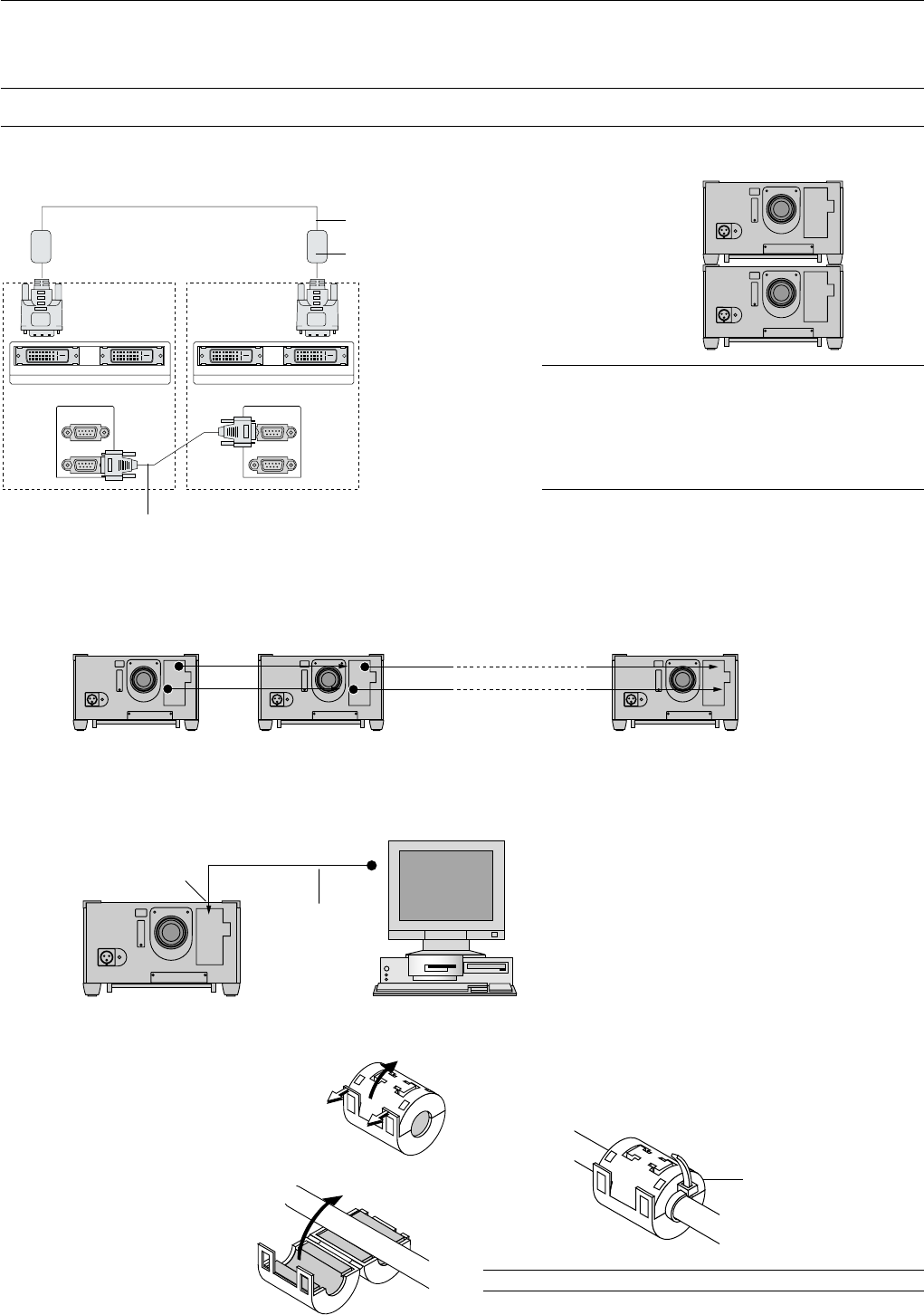
Using the RGB DIGITAL connectors
The Link mode function allows you to adjust or set multiple projectors using the RGB DIGITAL and OPTION connectors.
The DVI DIGITAL input accepts up to the SXGA (1280 x 1024 @75Hz) signal in Link mode.
NOTE: The Auto Adjust feature does not work for DVI digital signal. When DVI signal is selected and the image position is not corrected, adjust the horizontal and
vertical position using the Position screen. See page E-33 for more details.
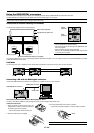
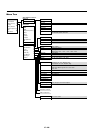
Connection for Double Stacking in Link Mode
DVI-D cable (supplied)
Connect source equipment to the master projector.
It is recommended that you use a commercially available distribution amplifier if you use signals other than VGA (640X480@60Hz) to SXGA
(1280X1024@75Hz) in Link mode.
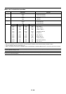
OPTION
IN
OUT
OPTION
IN
OUT
OUTPUT
RGB DIGITAL
INPUT9 OUTPUT
RGB DIGITAL
INPUT9
Master
projector
Slave
projector
Bi-directional RS-232C cable (not supplied)
Master projector Slave projector
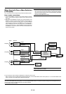
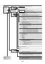
Link Mode
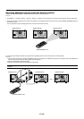
You can daisy-chain up to 16 projectors and operate them separately with the same remote control in wired operation.
Connecting a PC with the RGB digital connector
Connect the RGB DIGITAL IN connector of the projector to a digital connector of your computer.
RGB DIGITAL IN connector
DVI-D cable
RGB digital connector
NOTE:
* Use the supplied DVI-D cables for stacking.
* The end with the ferrite core should go to the RGB DIGITAL OUT-
PUT of the projector.
* Specify the DVI-D type when you buy DVI cable.
When you use commercially available DVI cables, they must be 5
m (16.4 feet) or less in length.
Master Slave1 Slave16
Supplied ferrite clamp core
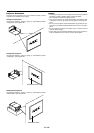
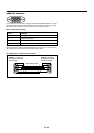
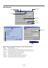
Installation Instructions
1. Open and attach the ferrite clamp core to the
supplied DVI-D cable as close as possible to
the end that goes to the projector.
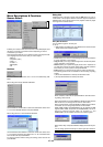
Information for Reducing Radiation of Electromagnetic Waves
To reduce unnecessary radiation of electromagnetic waves, use the supplied ferrite clamp core,
* Push the catch to open the ferrite clamp core.
2. Close the ferrite clamp core tightly.
Band
3. Fix the supplied band to the cable as a stopper.
* Pull the end of the band to tighten it. Cut off the surplus of the band.
NOTE: Be sure to use the ferrite clamp core at the end of the DVI-D cable.