Reference Manual for the Integrated ADSL Modem and Wireless Router with Voice, Model
2-10 Introduction
v1.0, September 2006
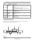
Viewed from left to right, the rear panel contains the following elements:
1. RJ-11 ADSL port for connecting the modem router to an ADSL-capable telephone wall jack
via the ADSL port of an ADSL filter/splitter.
2. PSTN (Public Service Telephone Network) port for connecting to a telephone wall jack via the
phone port of an ADSL filter/splitter.
3. Phone Ports for connecting to a telephones
4. Four Local Ethernet RJ-45 LAN ports for connecting the modem router to the local computers
5. Factory Default Reset push button
6. AC power adapter inlet
7. Wireless antenna
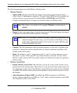
Each LAN port has two LEDs, one green and one amber. They indicate the port status as follows:
Connecting the Router to the Internet
To connect your Integrated ADSL Modem Wireless Router with Voice to the Internet, refer to the
Integrated ADSL Modem and Wirelesss Router Setup Manual on the resource CD or online at
http://documentation.netgear.com/dg834gv/enu/208-10042-01/index.html.
• On (Green) LAN port is linked to a 100Mbps device
• Blink (Green) Data is being transmitted or received at 100 Mbps
• On (Amber) LAN port is linked to a 10Mbps device
• Blink (Amber) Data is being transmitted or received at 10 Mbps
• Off No link is detected on this port


