


2-1physical description
CHAPTER 2: PHYSICAL DESCRIPTION
This chapter describes the hardware features of the FS726 and FS750 Switches.
Topics include:
• Front and back panels
• 10/100 Mbps RJ-45 ports
• LED Mode button and LEDs
• Module bays (for copper or fiber Gigabit Ethernet modules)
• Auto Uplink
• Reset button
Front and Back Panels
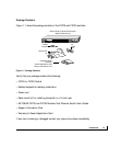
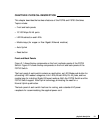
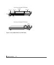
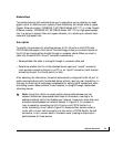
Figure 2-1 shows the key components on the front and back panels of the FS726
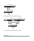
Switch. Figure 2-2 shows the key components on the front and back panels of the
FS750 Switch.
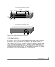
The front panel of each switch contains a reset button, an LED Mode push button for
alternating LED readout categories, Link LEDs, Mode LEDs, RJ-45 jacks, and two
module bays for installing Gigabit Ethernet modules. Both the FS726 Switch and the
FS750 Switch support Auto Uplink technology, eliminating the need for a
Normal/Uplink push button.
The back panel of each switch has fans for cooling, and a standard AC power
receptacle for accommodating the supplied power cord.