


figures viii
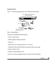
Figure 1-1. Package Contents 1-5
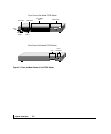
Figure 2-1. Front and Back Panels of the FS726 Switch 2-2
Figure 2-2. Front and Back Panels of the FS750 Switch 2-3
Figure 2-3. Creating Redundant Paths between
Network Devices (Example 1) 2-6
Figure 2-4. Creating Redundant Paths between
Network Devices (Example 2) 2-6
Figure 3-1. Example of Desktop Switching 3-1
Figure 3-2. Example of Segment Switching and Bridging 3-2
Figure 3-3. Example of Media Compatibility
and Conversion 3-3
Figure 4-1. Attaching Mounting Brackets 4-3
Figure 4-2. Connecting Devices to the Switch 4-4
Figure B-1. RJ-45 Plug and RJ-45 Connector
with Built-in LEDs B-1
Figure B-2 Duplex SC Cconnector and Duplex SC Plug B-3
Figure C-1. Straight-Through Twisted-Pair Cable C-4
Figure C-2. Crossover Twisted-Pair Cable C-4
Figure C-3. Category 5 UTP Cable with
Male RJ-45 Plug at Each End C-5
TABLES