


2-18 User’s Reference Guide
NN
NN
ee
ee
tt
tt
oo
oo
pp
pp
ii
ii
aa
aa
DD
DD
--
--
SS
SS
ee
ee
rr
rr
ii
ii
ee
ee
ss
ss
DD
DD
SS
SS
LL
LL
DD
DD
SS
SS
UU
UU
ss
ss
tt
tt
aa
aa
tt
tt
uu
uu
ss
ss
ll
ll
ii
ii
gg
gg
hh
hh
tt
tt
ss
ss
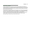
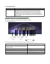
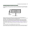
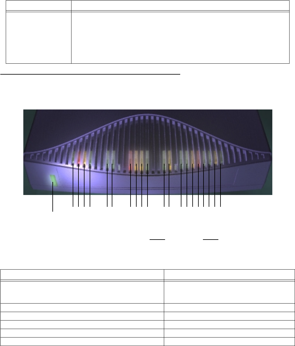
The figure below represents the Netopia D-Series status light (LED) panel.
Netopia D-Series LED front panel
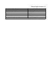
The following table summarizes the meaning of the various LED states and colors:
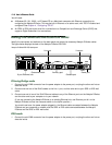
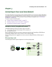
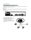
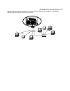
8-port Ethernet hub Eight 10Base-T Ethernet jacks. You will use one of these to configure the
Netopia D-Series. For a new installation, use the Ethernet connection.
Alternatively, you can use the console connection to run console-based
management using a direct serial connection. You can either connect your
computer directly to any of the Ethernet ports on the Netopia D-Series, or
connect both your computer and the Netopia D-Series to an existing Ethernet
hub on your LAN.
When this happens... the LEDs...
The corresponding line passes supervisory traffic between
the Digital Subscriber Line Access Multiplexer (DSLAM) and
the Netopia D-Series
2 or 8 flashes
yellow
.
The WAN interface is operational 3 or 9 is
green
.
The line is unavailable 3 or 9 flashes
red
.
The WAN on Channel 1 has carrier 4 or 10 is
green
.
Data is transmitted or received on the WAN on Channel 1 4 or 10 flashes
yellow
.
The WAN on Channel 2 has carrier 5 or 11 is
green
. (D3232 only)
Port Description
2 3 4 5 6 7 8 9 1011 12 13 14 15 16171819 2021
Management
Ready
Channel 1
Link/Receive
Console
Auxiliar
y
Collision
Traffic
WAN 1 WAN 2 Ethernet
Power
1
Channel 2
Management
Ready
Channel 1
Channel 2