


Making the Physical Connections 2-17
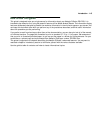
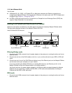
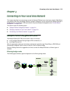
2. Connect one end one of the RJ-45 cables to the Line 1 port, and the other end to your SDSL or IDSL wall
outlet.
3. Connect one end of one of the RJ-45 Ethernet cables to any of the Ethernet ports on the Netopia D-Series
and the other end to your computer or to your network.
(If you are connecting the Netopia D-Series to an existing Ethernet hub, use Ethernet port #1 on the
Netopia D-Series and set the crossover switch to the
Uplink
position.) This connection will provide
management access to the Netopia D-Series.
4. Connect the HD-15 end of the supplied V.35 interface cable to the Auxiliary port and the other end to your
external Frame Relay router. The unit will auto-detect filtering bridge mode or DSU mode, based on which
cables are connected and traffic on the lines.
CC
CC
oo
oo
nn
nn
nn
nn
ee
ee
cc
cc
tt
tt
LL
LL
ii
ii
nn
nn
ee
ee
pp
pp
oo
oo
rr
rr
tt
tt
ss
ss
tt
tt
oo
oo
mm
mm
uu
uu
tt
tt
ii
ii
pp
pp
ll
ll
ee
ee
DD
DD
SS
SS
LL
LL
ll
ll
ii
ii
nn
nn
ee
ee
ss
ss
((
((
DD
DD
33
33
22
22
33
33
22
22
oo
oo
nn
nn
ll
ll
yy
yy
))
))
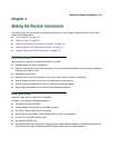
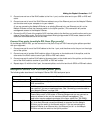
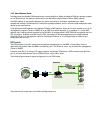
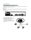
On the Netopia D3232 DSU, you can connect the Line ports to up to 4 DSL lines using the splitters provided
with your equipment.
1. Connect one end of one of the RJ-45 cables to the Line 1 port, and the other end to the port on the single
end of the splitter.
2. Connect one end of another RJ-45 cable to either of the ports on the double end of the splitter, and the
other end of the RJ-45 cable to one of your SDSL or IDSL wall outlets.
3. Connect one end of another RJ-45 cable to the second port on the double end of the splitter, and the other
end of the RJ-45 cable to another of your SDSL or IDSL wall outlets.
4. Repeat steps 1-3 with the Line 2 port, the second splitter, and a third and fourth SDSL or IDSL wall outlets.
NN
NN
ee
ee
tt
tt
oo
oo
pp
pp
ii
ii
aa
aa
DD
DD
--
--
SS
SS
ee
ee
rr
rr
ii
ii
ee
ee
ss
ss
DD
DD
SS
SS
LL
LL
DD
DD
SS
SS
UU
UU
bb
bb
aa
aa
cc
cc
kk
kk
pp
pp
aa
aa
nn
nn
ee
ee
ll
ll
pp
pp
oo
oo
rr
rr
tt
tt
ss
ss
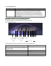
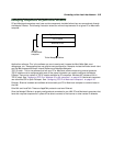
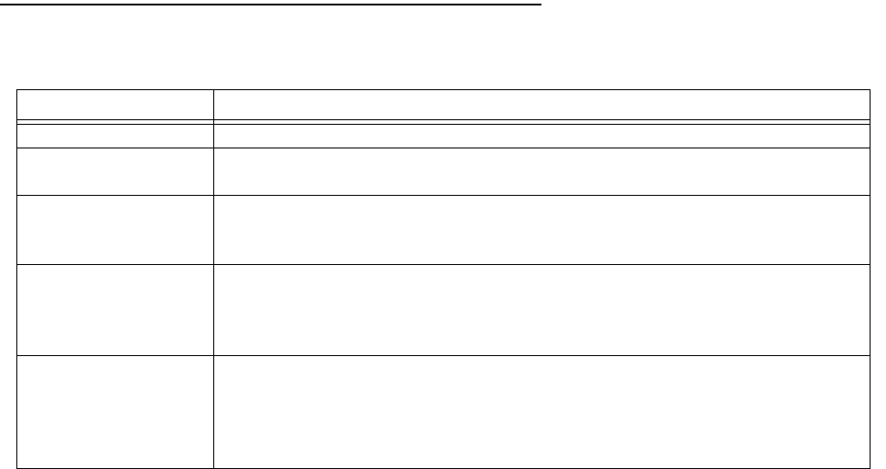
The following table describes all the Netopia D-Series DSL DSU back panel ports.
Port Description
Power port A mini-DIN8 power adapter cable connection.
Line port 1 and 2 Two RJ-45 telephone-style jacks labelled Line 1 and Line 2 for your SDSL or
IDSL connections.
Console port A DE-9 console port for a direct serial connection to the console screens. You
can use this if you are an experienced user. See “Connecting a console cable to
your Netopia D-Series” on page 5-36.
Auxiliary port An HD-15 auxiliary port for attaching the V.35 interface cable to an external
Frame Relay router in DSU mode. In Filtering Bridge mode you can connect an
external modem to this port for remote out-of-band management. This
application requires separate purchase of the Async cable (Part TE6/DB25).
Crossover switch A crossover switch with Normal and Uplink positions. If you use Ethernet Port
#1 for a direct Ethernet connection between a computer and the Netopia
D-Series, set the switch to the
Normal
position. If you are connecting the
Netopia D-Series to an Ethernet hub, use Ethernet port #1 on the Netopia
D-Series and set the switch to the
Uplink
position.