


10003137.00 Rev.1
1-4 Overview
Overview
The PrimeSwitch ISDN Protocol Analyzer Package (PAP) monitors and displays layer 1,
layer 2 and layer 3 protocol activity on a PrimeSwitch ISDN interface.
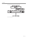
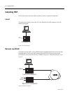
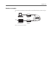
PAP uses COM ports on the PC to transfer information to and from a PrimeSwitch ISDN
module. PAP can monitor multiple ISDN interfaces on PrimeSwitch 100 Series modules
which have more than one (for example, the DTM or QBRM), and can use either COM1,
COM2 or BOTH at the same time on the PC.
When PAP is operating, all traffic entering the analyzer system, either from the ISDN or
from a captured file, is filtered, buffered and displayed.
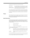
Filtering
When you enable a filter, every message passing through the analyzer passes through
the filter. Traffic that is selected by the filter enters the buffer. Traffic that is not selected
is lost. Filters select or reject system, layer 1, layer 2 and layer 3 as follows:
• System messages are information from other system modules. They can be on or off,
but are generally not of concern to users.
• Layer 1 status change messages can be on or off.
• Layer 2 is filtered on frame type, for example, SABME and RR. They can be on, off,
enabled for all except a defined list or enabled for a defined list only.
• Layer 3 is filtered on message type, for example, SETUP and RELease. They can be
on, off, enabled for all except a defined list or enabled for a defined list only.
You create a filter with the MakeF command and display the current filter with the
ShowF command (see Chapter 4 — Commands for more information). You can store
several filters on disk but only one filter can be enabled at a time.
Buffering
After passing through the filter, messages are stored in the internal ‘first in first out’ (FIFO)
buffer. Messages are also written to disk if you have enabled capturing. The full contents
of each traffic item are stored irrespective of the current decoding and display settings.
When the display is paused, traffic continues to be written to the buffer.
Items in the buffer are numbered sequentially from zero until the buffer is full, then from
zero again. This number appears alongside the message when it is displayed.
Use the Save command to write the contents of the buffer to disk (see
Chapter 4 — Commands for more information).
The buffer is dynamically allocated from the PC’s memory. The default is to use Extended
or Expanded memory, if it is available, and to use up all but 80 Kbytes of conventional
memory if the Extended or Expanded memory is not available.