


NTI RACKMUX Console Drawer with UNIMUX Switch
20
CASCADING
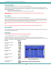
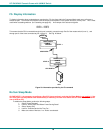
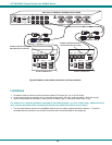
The UNIMUX can be cascaded as shown in Fig. 21 below. Single user or multi-user UNIMUX switches may be connected
downstream (see Figs. 23 and 24). The first switch in a cascaded system is referred to as the "master", while all downstream
switches are referred to as "slaves". The only additional hardware required to cascade switches is a set of device and monitor
cables for each “SLAVE UNIT” (USB-VEXT-xx-MM). All CPUs and switches can then be controlled by users using OSD
commands with Command Mode.
Notes:
• The UNIMUX used in a RACKMUX cannot be connected in a cascaded system with UNIMUX-USBV-x switches made
prior to 10-1-04.
• Slaves in a cascaded system must be either all single-user switches or all multi-user switches, but not a
combination of both.
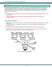
Cascaded Installation
a. Using the 15HD video cable ends of a USBVEXT-xx-MM cable, connect the USB KVM slave's MONITOR port to the master’s
VIDEO 1 port.
b. Using the USB ends of the same USBVEXT-xx-MM cable, connect one of the USB slave’s USB DEVICES ports to the
master’s CPU 1 port.
Note: Only one of the two ports labeled DEVICES on a slave needs to be used in order for cascading to work.
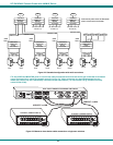
c. Repeat step b. & c. for each additional slave, keeping in mind that each slave will connect to the next available master’s
port (i.e. Slave #2 to master’s VIDEO 2 & CPU 2, etc.) See Fig. 24 on page 22.
Figure 21- Connections for Cascading
.
(slave unit 1) (slave unit 2)
(slave unit 3)
(master unit)
USB-VEXT-xxMM
USBVEXT-xx-MM
USB
CPU
UNIMUX-USBV-8
USB
CPU
USB
CPU
USB
CPU
USB
CPU
USB
CPU
USB
CPU
USB
CPU
USBVEXT-xx-MM
U
S
B
V
E
X
T
-
x
x
-
M
M
U
S
B
V
E
X
T
-
x
x
-
M
M
USB-VEXT-xxMMUSB-VEXT-xxMM
UNIMUX-USBV-8 UNIMUX-USBV-8
UNIMUX-USBV-8