


NTI RACKMUX Console Drawer with UNIMUX Switch
22
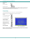
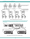
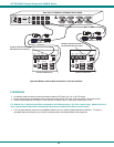
Figure 24- Master to slave cable connections- multi-user switches
Limitations
¾ All switches used as slaves must have the same number of CPU ports (all 4, 8, or 16 CPU ports).
¾ Up to 8 slaves may be connected to form a maximum system size of 152 ports (1x32 port master + 8x16 port slaves).
¾ Slaves must be added to the master in order (slave #1 to master’s port 1, slave #2 to master’s port 2, etc).
FYI: Master Port 1 (with an 8-port Slave connected to it) will become ports 1-8 (1-4 for a 4-port slave). Master Unit Port 2
(with a second 8-port Slave Unit connected) will become port numbers 9-16 (5-8 for a 4-port slave).
¾ The front panel buttons (found on most UNIMUX switches) are only used to operate standalone switches. To control a
cascaded network of switches, only the OSD commands within Command Mode will be recognized.
M O N IT O R 1
M O N IT O R 2
M O N IT O R 3
M O N IT O R 4
U S E R 1
U S E R 2
U S E R 3U S E R 4
R
S
2
3
2
N T I
R
C P U 1 6
M O N IT O R 1
M O N IT O R 2
M O N IT O R 3
M O N IT O R 4
U S E R 1
U S E R 2
U S E R 3U S E R 4
R
S
2
3
2
N T I
R
C P U 1 6
S L A V E # 2 U N I M U X 4 X 1 6 S L A V E # 1 U N I M U X 4 X 1 6
U S B V E X T - x x - M M
U S B V E X T - x x - M M
C O N N E C T M A S T E R C P U P O R T 1
T O O N E U S E R P O R T O N S L A V E 1
C O N N E C T M A S T E R C P U P O R T 2
O N E U S E R P O R T O N S L A V E 2
-
+
C P U 4
C P U 3
C P U 2 C P U 1
C P U 8
C P U 7
C P U 6 C P U 5
8 4
7 3 6 2 5 1
V ID E OV ID E O
N E T W O R K T E C H N O L O G IE S
IN C
T e l:3 3 0 -5 6 2 -7 0 7 0
1 2 7 5 D a n n e r D r, A u r o ra , O H 4 4 2 0 2
w w w .n ti1 .c o m
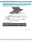
R e a r V i e w o f U N I M U X i n R A C K M U X - U W 1 5 - 8 U S B
N T I
T el:330 -56 2-70 70
F ax :33 0-56 2 -19 9 9
12 75 D a n n er D r
A u ro ra, O H 44 20 2
w w w .nti1.co m
R
1 2 V D C