


MAN031 Rev Date 2/12/2007
TABLE OF FIGURES
Figure 1- Mount RACKMUX to rack...................................................................................................................................................4
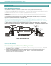
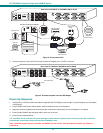
Figure 2- Connect each CPU.............................................................................................................................................................5
Figure 3- Connect the power cord and AC adapter ...........................................................................................................................5
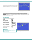
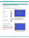
Figure 4- Administrator Login screen.................................................................................................................................................7
Figure 5- User Login screen ..............................................................................................................................................................7
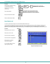
Figure 6- Administration Mode menu.................................................................................................................................................8
Figure 7- Administrator password change .........................................................................................................................................8
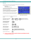
Figure 8- User Name List screen.......................................................................................................................................................9
Figure 9- Edit the user access list....................................................................................................................................................10
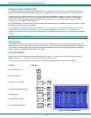
Figure 10- Command Mode screen .................................................................................................................................................11
Figure 11- More Command Mode Features.....................................................................................................................................12
Figure 12- Edit Mode screen............................................................................................................................................................13
Figure 13- Change Settings menu...................................................................................................................................................14
Figure 14- Select ports for broadcasting..........................................................................................................................................15
Figure 15- Select ports for scanning................................................................................................................................................15
Figure 16- Select the keyboard language ........................................................................................................................................16
Figure 17- Configure Ports for MAC screen.....................................................................................................................................16
Figure 18- Search Mode screen ......................................................................................................................................................17
Figure 19- Maintenance Mode screen .............................................................................................................................................17
Figure 20- Information provided by the F3 command ......................................................................................................................19
Figure 21- Connections for Cascading.............................................................................................................................................20
Figure 22- Cascaded configuration with multi-user slaves...............................................................................................................21
Figure 23- Master-to-slave device cable connections- single-user switches....................................................................................21
Figure 24- Master to slave cable connections- multi-user switches..............................................................
...................................22
Figure 25- Locating the password reset button................................................................................................................................25