


6800/7000 Series - Distribution and Routing Products Installation and Operation Manual 39
User Interface Chapter 4: USM-6800 PAL/NTSC Monitoring Encoder Module
User Interface
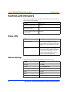
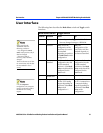
The following chart describes the Mode Select switch and Toggle switch
functions:
Mode Select Switch Toggle Switch
Position Function Down Up
0Operate
•Normal operation; Tog gl e switch disabled.
• Store any changed settings to *EEPROM.
1 Standard Force: Forces the
configuration of the
board into 525 or 625
line standard
depending on position
2 of Mode Select switch
configuration.
Auto: The
configuration of the
board 525 or 625 line
standard depends on
the detected standard.
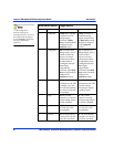
2Force
Standard
625: Forces the board
configuration into the
625 line standard.
Position 1 of the Mode
Select switch should be
configured for the
Force mode.
525: Forces the board
configuration into the
525 line standard.
Position 1 of the Mode
Select switch should be
configured for the
Force mode.
3RESERVED
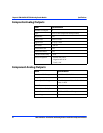
4OutputComponent: Generates
RGB or YUV analog
outputs depending on
position 6 of the Mode
Select switch
configuration.**
Composite: Generates
the YC=2 composite or
Y composite analog
outputs depending on
position 5 of the Mode
Select switch
configuration.
Data is stored to the
*EEPROM under the
following conditions:
-
Any change in the Mode
Select switch position, only if
data has changed.
-After 30 seconds of
inactivity, only if data has
changed.
There are discrete sets of data
for 525 and 625; only the data
for the standard in use is
stored.
**In the Component
configuration, one composite
output is generated as well as
the RGB or YUV analog
outputs.