


Chapter 8: VPD-6830 Programmable Video DA Series VPD-6830-CLP
70 6800/7000 Series - Distribution and Routing Products Installation and Operation Manual
VPD-6830-CLP
Configuration
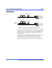
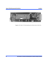
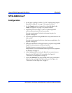
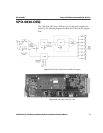
1. Set the input coupling for either AC or DC coupling using jumpers
J2 and J3. See Figure 8-3 on page 71 for jumper locations.
2. Set the Clamping mode on jumper J1 to either Soft, Hard or No
Clamp. See Figure 8-3 on page 71 for jumper location.
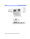
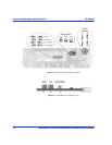
3. Adjust the gain over a range of -3 dB to +3 dB using the R5
multi-turn potentiometer in the base module.
Turn the potentiometer Clockwise to Increase the gain. See
Figure 8-4 on page 71.
4. Adjust the equalization using the R6 multi-turn potentiometer in the
base module.
Turn the potentiometer clockwise to obtain more equalization. See
Figure 8-4 on page 71.
5. Make fine adjustments to the high-frequency response using the R21
Single-Turn potentiometer in the base module.
The high-frequency response is factory-set/calibrated.
Readjustment is not recommended without precise test equipment.
See Figure 8-4 on page 71.
6. Adjust the Hard clip level using the R4 multi-turn potentiometer
located on the VPD-6830-CLP submodule. See Figure 8-3
“
VPD-6830-CLP Configuration” on page 71.
7. Adjust the Luminance clip using the R13 multi-turn potentiometer
located on the card edge of the submodule card. See Figure 8-4
“
VPD-6830-CLP Card-Edge View” on page 71.