


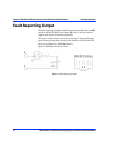
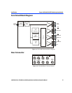


Chapter 4: USM-6800 PAL/NTSC Monitoring Encoder Module User Interface
40 6800/7000 Series - Distribution and Routing Products Installation and Operation Manual
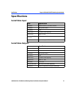
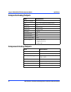
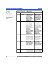
5Composite2 comp+YC: Generates
2 composite and YC
analog outputs.
Position 4 of Mode
Select switch should be
configured for the
Composite mode.
4 comp: Generates 4
composite analog
outputs. Position 4 of
the Mode Select switch
should be configured
for the Composite
mode.***
6 Component RGB: Generates RGB
analog output. Sync is
present on all of the
outputs. On-board
potentiometer allows
the adjustment of
overall gain and each
channel gain
independently.
Position 4 of the Mode
Select switch should be
configured for
Component output.
YUV: Generates YUV
analog outputs. Sync is
present on the Y
output. On-board
potentiometer allows
the adjustment of the
overall gain and each
channel gain
independently.
Position 4 of the Mode
Select switch should be
configured for
Component output.
7V BlankingBlank: All of the
information in the VBI
is blanked: Up to line
20 in 525 line standard,
up to line 23 in the 625
line standard.
Pass: All of the
information in the VBI
is passed without
processing for digital
to analog output.
8SetupOff: The 7.5 IRE
pedestal is not inserted
into the analog video in
525 line standard.
On: The 7.5 IRE
pedestal is inserted
into the analog video in
the 525 line standard.
9BurstOff: The burst is turned
off in the 525 or 625
line standards.
On: The burst is turned
on in the 525 or 625
line standards.
AChromaOff: The chrominance
is turned off in the 525
or 625 line standards.
On: The chrominance
is turned on in the 525
or 625 line standards.
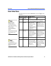
Mode Select Switch Toggle Switch
Position Function Down Up
***This configuration
decreases board power
consumption from 5.4 to 5.0 W
and requires that the jumpers
be set to Position B. In all other
cases, they should be in
position A.