


6800/7000 Series - Distribution and Routing Products Installation and Operation Manual 61
Configuration Chapter 7: VEA-6840 Video Equalizing Amplifier Module
Configuration
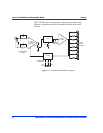
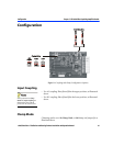
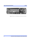
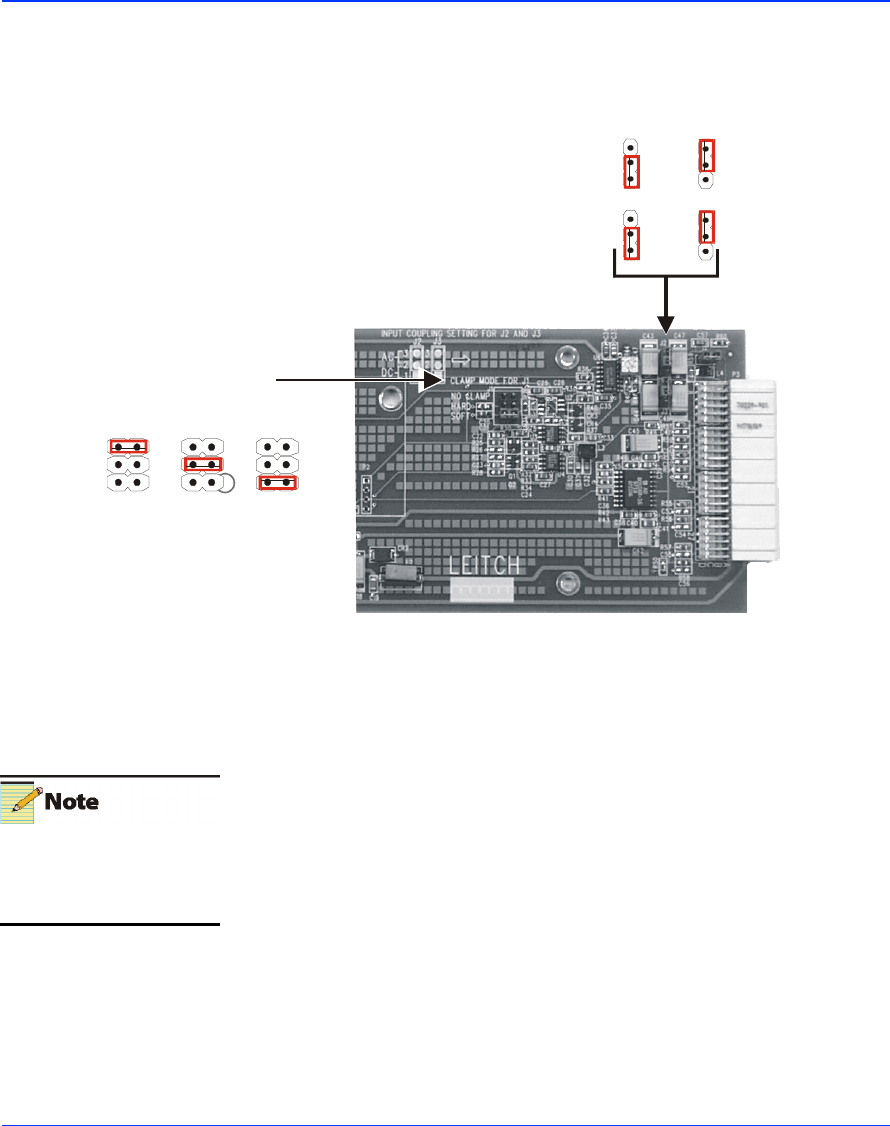
Figure 7-2. Coupling and Clamp Configuration Options
Input Coupling
• For AC coupling: Place J2 and J3 in the upper position, as illustrated
above.
• For DC coupling: Place J2 and J3 in the lower position, as illustrated
above.
Clamp Mode
Clamping can be set to No Clamp, Hard, or Soft clamp via Jumper J1, as
illustrated above.
DC AC
J3 J3
J2 J2
Input Coupling
J3 J3J3
SOFTHARD
NO
CLAMP
Clamp Mode
Shunt positions for Clamp
Mode and Input Coupling are
illustrated by the symbols
printed on the circuit board.