


8692omSF module 133
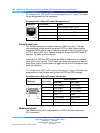
Connection to TXD and RXD signals and GND is sufficient for the console
serial port to fully function. The Console port does not support any inbound
flow control; that is, the port does not toggle control lines to indicate an input
buffer full condition.
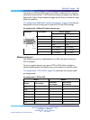
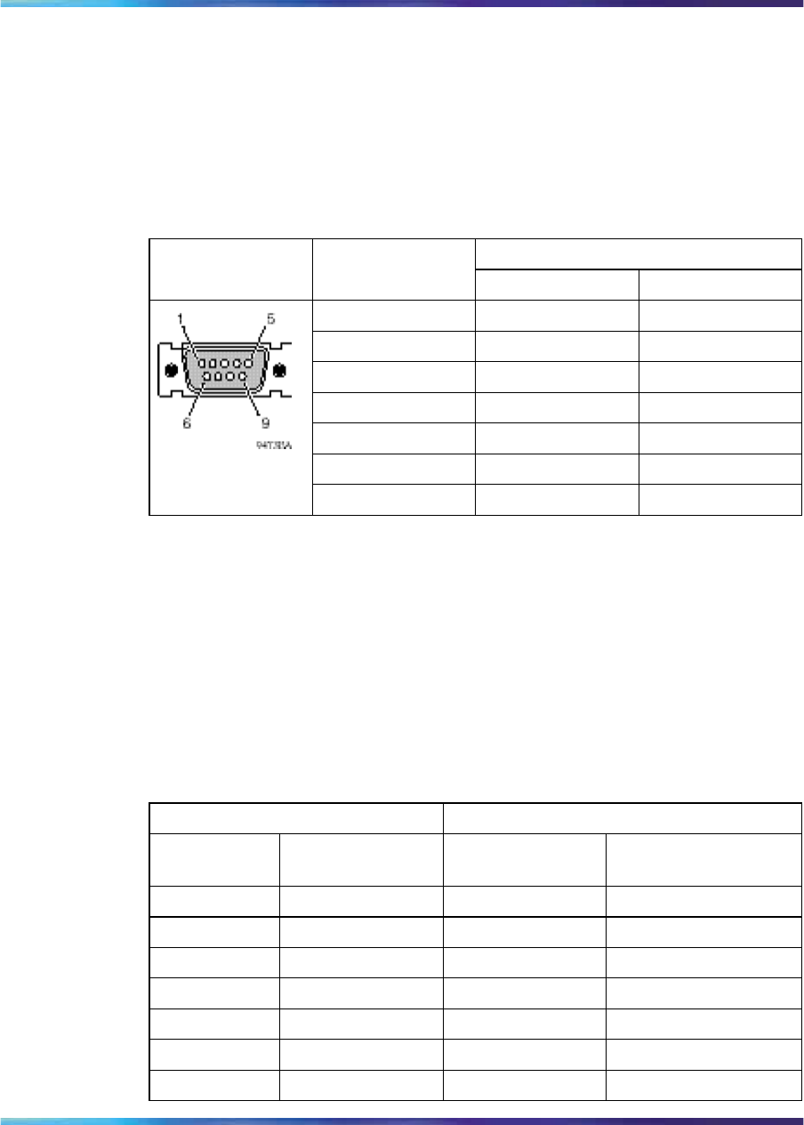
"Pin assignments: 8692omSF module Console port" (page 133) lists the pin
assignments for the Console port for both the DTE and DCE settings.
Pin assignments: 8692omSF module Console port
Switch position
Connector
Pin number
DCE (left)
DTE right)
2
TXD (Output) RXD (Input)
3
RXD (Input) TXD (Output)
4
DSR (Input) DTR (Output)
5
GND GND
6
DTR (Output) DSR (Input)
7
CTS (Input) RTS (Output)
8
RTS (Output) CTS (Input)
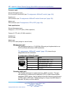
Modem serial port
The Modem serial port is implemented on a DB-9 connector wired as a
DTE connection.
To set up modem access, you need a DTE-to-DCE cable ( straight or
transmit cable) between the Modem port and a modem or terminal server.
"Pin assignments: DTE to DCE" (page 133) describes the required cable
pin assignments.
Pin assignments: DTE to DCE
Switch
Modem
Signal
Pin number
DCE DB-9
pin number
DCE DB-25
pin number
RXD
223
TXD
332
DTR
4420
GND
557
DSR
666
RTS
77
4
CTS
88
5
Nortel Metro Ethernet Routing Switch 8600
Installation — Modules
NN46220-306 02.02 Standard
4.2 7 July 2008
Copyright © 2005-2007, Nortel Networks
.