


8691omSF module 65
8691omSF module LEDs
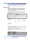
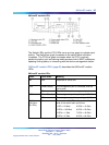
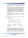
The Switch LEDs and the CPU LEDs serve as a bar graph to indicate card
activity. The Switch bar graph increases as the switch fabric utilization
increases. The CPU bar graph increases when the CPU is actively
performing tasks, such as learning media access control (MAC) addresses,
updating routing tables, or interacting with the device management station.
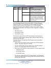
"8691omSF module LEDs" (page 65) describes the 8691omSF module
LEDs.
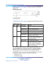
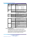
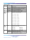
8691omSF module LEDs
Label
Color/State
Meaning
Mz N/A Reserved for future use.
Green/Steady The management port is connected, and the
link is good.
Link
Off There is no link to the management port.
Green/Steady The management port is operating at 100 Mb/s.
100
Off The management port is operating at 10 Mb/s.
The number of lit LEDs indicates the utilization
level of the switch fabric as follows:
1 LED = 10 Mb/s 5 LEDs = 10 Gb/s
2 LEDs = 100 Mb/s 6 LEDs = 20 Gb/s
3 LEDs = 1 Gb/s 7 LEDs = 40 Gb/s
Switch
Utilization
(8 LEDs)
Green
4 LEDs = 5 Gb/s 8 LEDs = 64 Gb/s
Nortel Metro Ethernet Routing Switch 8600
Installation — Modules
NN46220-306 02.02 Standard
4.2 7 July 2008
Copyright © 2005-2007, Nortel Networks
.