


Installing ISDN BRI hardware for line applications 29
Each SILC provides eight four-wire full-duplex ports. These ports
are connected to building wiring to for m DSLs. These ports are
polarity-sensitive. Signal polarity must be maintained along each loop.
Each UILC provides eight two-wire full-duplex ports. These ports are
connected to twisted pair building wiring to form DSLs. These DSLs are
not polarity-sensitive and, although recommended, it is not necessary to
maintain signal polarity along each loop.
Procedure 9
Cross-connecting SILC and/or UILC ports to the building wiring
Step Action
Perform the following steps to cross-connect the SILC and/or UILC ports
to the building wiring.
1
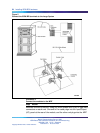
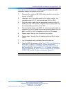
Identify the card type (SILC or UILC) for a connector on the MDF.
Refer to the IPE or CE module card location form at the end of this
chapter, which shows the card type connected to each I/O panel
connector.
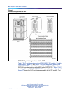
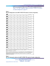
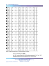
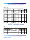
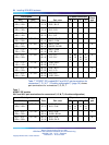
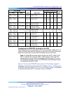
2
Identify transmit and receive pairs on the top of the labeled
distribution strip for the card type and module type you are
connecting. To identify SILC or UILC ports and their pin
numbers, refer to Table 5 "NT8D37 IPE moduleSILC and UILC
pair-terminations for connectors A, E, K, R (12-cable configuration)"
(page 33) through Table 11 "Card location form: NT8D37 IPE
module (12-cable configuration)" (page 44), which begins on
Table 5 "NT8D37 IPE moduleSILC and UILC pair-terminations for
connectors A, E, K, R (12-cable configuration)" (page 33).
Note: In Table 5 "NT8D37 IPE moduleSILC and UILC
pair-terminations for connectors A, E, K, R (12-cable
configuration)" (page 33) through Table 11 "Card location
form: NT8D37 IPE module (12-cable configuration)" (page 44),
the cable pair designated T- T+ is the transmit pair and the
pair designated R+ R- is the receive pair of the S/T interface.
The cable pair designated T R is the Tx and Rx of the 2B1Q
full-duplex U interface.
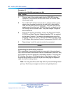
3
Identify building wires connected to the bottom of the distribution
strip. Refer to the Building Cable Plan, which identifies wires
between distribution frames and wall outlets. The Building Cable
Plan is developed according to instructions in the "Planning the Site"
section in Communication Server 1000M and Meridian 1 : Large
System Planning and Engineering (553-3021-120).
4
Plug in the terminating resistor at the appropriate location in each
S/T DSL. See "Engineering Guidelines" in the ISDN Basic Rate
Nortel Communication Server 1000
ISDN Basic Rate Interface Installation and Commissioning
NN43001-318 01.02 Standard
Release 5.0 20 June 2007
Copyright © 2003-2007, Nortel Networks
.