


76 Configuring ISDN BRI hardware
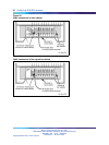
Note 1: Power Source 1 (PS1): Up to 2 Watts of power is supplied by
the SILC to the terminals on the DSL. This power is simplexed over the
TX and RX pairs provided by -48 V (-40 V for Europe) supply on the
SILC. The RX pair is positive with respect to the TX pair.
Note 2: Power Sink 2 (PS2) provides an optional means of powering
the terminal from a common supply in the wiring closet.
Note 3: Power Source 3 (PS3) provides the power from the terminal to
the NT1 if the NT1 does not have a local power source.
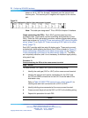
U interface specification
The U interface uses a 2-conductor, twisted pair cable terminated with
an RJ-45 type jack. An RJ-45 type jack on the NT1 device connects the
terminal to the DSL using this twisted pair cable.
The connector pin assignments for the jack and the plug are shown in Table
18 "U interface connector specification" (page 76). The table also shows
signal names for each interface pin at the UILC and at the terminal.
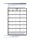
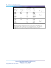
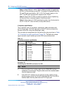
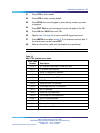
Table 18
U interface connector specification
Pin number
RJ45 jack
pin signal name
UILC
signal name
1
Not used No connection
2
Not used No connection
3
Not used No connection
4
Tip or Ring Tip or Ring
5
Tip or Ring Tip or Ring
6
Not used No connection
7
Not used No connection
8
Not used No connection
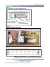
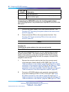
Procedure 23
Connecting the ISDN BRI terminals to the DSL
Step Action
1
Plug one end of the modular cable into the ISDN BRI interface
connector on the terminal. Plug the other end of the modular cable
into the telephone outlet.
2
If the SILC S/T interface has an optional auxiliary power source,
plug the power source into the wall outlet and then the 10-m (33-ft)
modular cable into the power source’s RJ-45 type jack.
Nortel Communication Server 1000
ISDN Basic Rate Interface Installation and Commissioning
NN43001-318 01.02 Standard
Release 5.0 20 June 2007
Copyright © 2003-2007, Nortel Networks
.