


MCS 2-server Sun Fire V100 Solaris Installation and Commissioning Guide
29
Copyright © 2006 Nortel Networks
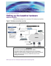
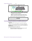
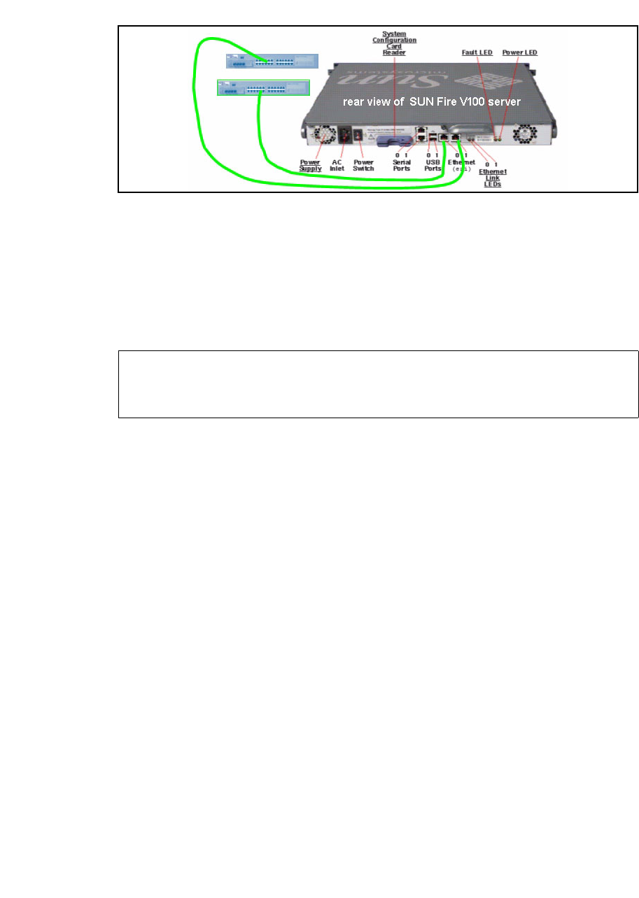
Figure 6 Sun Fire V100 server cabling to layer-2 switch
Note 1: Net 0 and Net 1 are for redundancy. It is preferable
that each Ethernet port get cabled to a different layer-2 switch,
if available, for maximum redundancy.
Note 2: The two Ethernet switches are physically linked
together through either cascade modules or Ethernet links.
2 Plug in the power cords at the back of the V100 server.
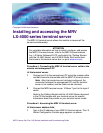
Connecting the Sun Fire V100 server to the MRV LX terminal server
The MCS 5100 platform uses the Sun Fire V100 server medium
configuration.
Note: This server is only available in an AC power configuration.
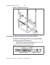
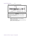
Procedure 3 Connecting the serial port on the V100 to the MRV LX
terminal server
At the back of the Sun Fire V100 server,
1 Connect the Sun Fire V100 server A/LOM serial port and B-
serial port to the MRV LX terminal server:
ATTENTION
Do not power up the server at this time.