


Tegra 200 Series Developer Board User Guide
DG-04927-001_v01 Advance Information – Subject to Change 26
NVIDIA CONFIDENTIAL
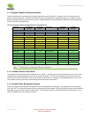
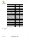
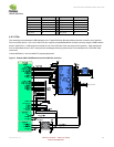
Table 8. ULPI Pinout
Signal Pin
Signal Pin
ULPI_CLK M2 ULPI_DATA2 N4
ULPI_DIR M3 ULPI_DATA3 L3
ULPI_NXT M1 ULPI_DATA4 L4
ULPI_STP P3 ULPI_DATA5 L6
ULPI_DATA0 P4 ULPI_DATA6 P5
ULPI_DATA1 P6 ULPI_DATA7 N6
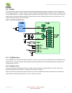
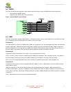
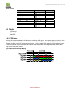
4.5.3 PCIe
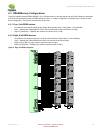
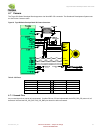
The remaining two downstream USB interfaces on the Tegra 200 Series Developer Board are each routed to one of the Mini-
PCIe connectors shown. One use for Mini-PCIe is to support compatible Baseband modules (currently using the USB interface
portion of Mini-PCIe). A SIM socket is provided off one of the PCIe Mini Card connectors for this purpose. Other peripherals
such as Solid-State drives or Wi-Fi may also take advantage of the high performance PCIe interfaces on the PCIe Mini Card
connectors.
Contact NVIDIA for a list of certified PCI express peripherals.
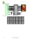
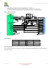
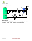
Figure 14. Example LAN9514 USB/Ethernet Hub and Dual Mini-PCIe Connectors