


Tegra 200 Series Developer Board User Guide
DG-04927-001_v01 Advance Information – Subject to Change 6
NVIDIA CONFIDENTIAL
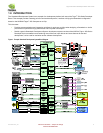
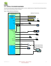
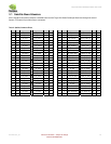
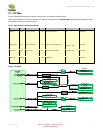
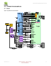
2.0 DEVELOPER BOARD OVERVIEW
2.1 Feature List
Applications Processor
NVIDIA Tegra 250, 23x23mm ,0.8mm pitch
DRAM and Flash Memory
8, 128Mx8, DDR2 @ 333MHz
TPS51116RGET DDR2 Buck Regulator
Hynix 8-bit NAND on board
Internal SD/MMC socket supports eMMC module
Baseband
USB based PCIe Mini Card Modules
USIM Card Connector
Display
LVDS Bridge: TI SN75LVDS83B
HDMI (Type A connector)
Slim 15-pin VGA Connector
Audio
Wolfson WM8903L Codec
Stereo Headphones
External and Internal Mics
Left/Right Speaker Amps.
Imaging
Dual-lane MIPI CSI connection for camera module
Wireless
Murata WiFi and Bluetooth module
- Bluetooth: CSR BC6
- 802.11b/g WiFi: Atheros 6002
-
SD/SDIO and HSMMC
Standard SD/SDIO/MMC socket
USB and Ethernet
SMSC LAN 9514 USB Hub and Ethernet
- 3 USB Type A Host ports
- USB for PCIE MiniCard Slot 2
- Ethernet RJ-45 Jack
SMSC USB3315 ULPI PHY
- USB for PCIE MiniCard Slot 1
USB Mini Type B connector for Recovery Mode
Buttons, Switches
Power-On, Reset and Force-Recovery Buttons
Miscellaneous Devices
EC: SMSC MEC1308
Temperature Sensor: ADT7461AARMZ_RL7
Power
PMIC: TI TPS658621AZGUR
Battery Charge Controller: TI BQ24745RHDR
Main s
ystem regulators
- 3.3V, 5V, 1.8V and 1.05V
Other, lower power regulators
3.3V (standby), 1.2V and 1.5V
Debug / Test Features
22-pin Debug Connector
- JTAG, UART and SPI
Tegra Debug Module (optional)
This is an optional module that may have been shipped with
your Tegra 200 Series Developer Board depending on the
version of the development kit that was ordered.
Power, Reset and Force-Recovery Buttons
Lid Open/Close slider switch
UART4 (4-pin UART) brought to RS232 DB9 serial
connector (intended for software test and debug)
Adds a coin cell battery for uninterrupted Real-Time
Clock operation when the developer board is
powered off