


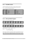
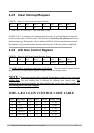
2.4.5 Clear Interrupt Request
(WRITE) Base+8: Clear Interrupt Request Format
Bit 7 Bit 6 Bit 5 Bit 4 Bit 3 Bit 2 Bit 1 Bit 0
X X X X X X X X
X = don‘t care, XXXXXXXX = any 8 bit data is valid
If OME-A-8111 is working in the interrupt transfer mode, an on-board hardware status bit
will be set after each A/D conversion. This bit must be cleared by the software before next
hardware interrupt. Writing any value to address BASE+8 will clear this hardware bit and
the hardware will generate another interrupt when next the A/D conversion is completed.
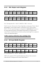
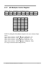
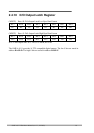
2.4.6 A/D Gain Control Register
(WRITE) Base+9: A/D Gain Control Register Format
Y Bit 6 Bit 5 Bit 4 Bit 3 Bit 2 Bit 1 Bit 0
X X X X X GAIN2 GAIN1 GAIN0
The OME-A-8111 provides a gain factor of 1/2/4/8/16. The gain controls register control
the gain of the A/D input signal. Bipolar/Unipolar will affect the gain factor.
NOTE : If the gain control code is changed, the hardware needs to have extra gain
settling time. The gain settling time is different for different gain control code. The
software driver does not monitor the gain settling time, so the user needs to delay the
gain settling time if the gain changed.
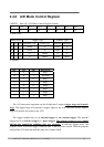
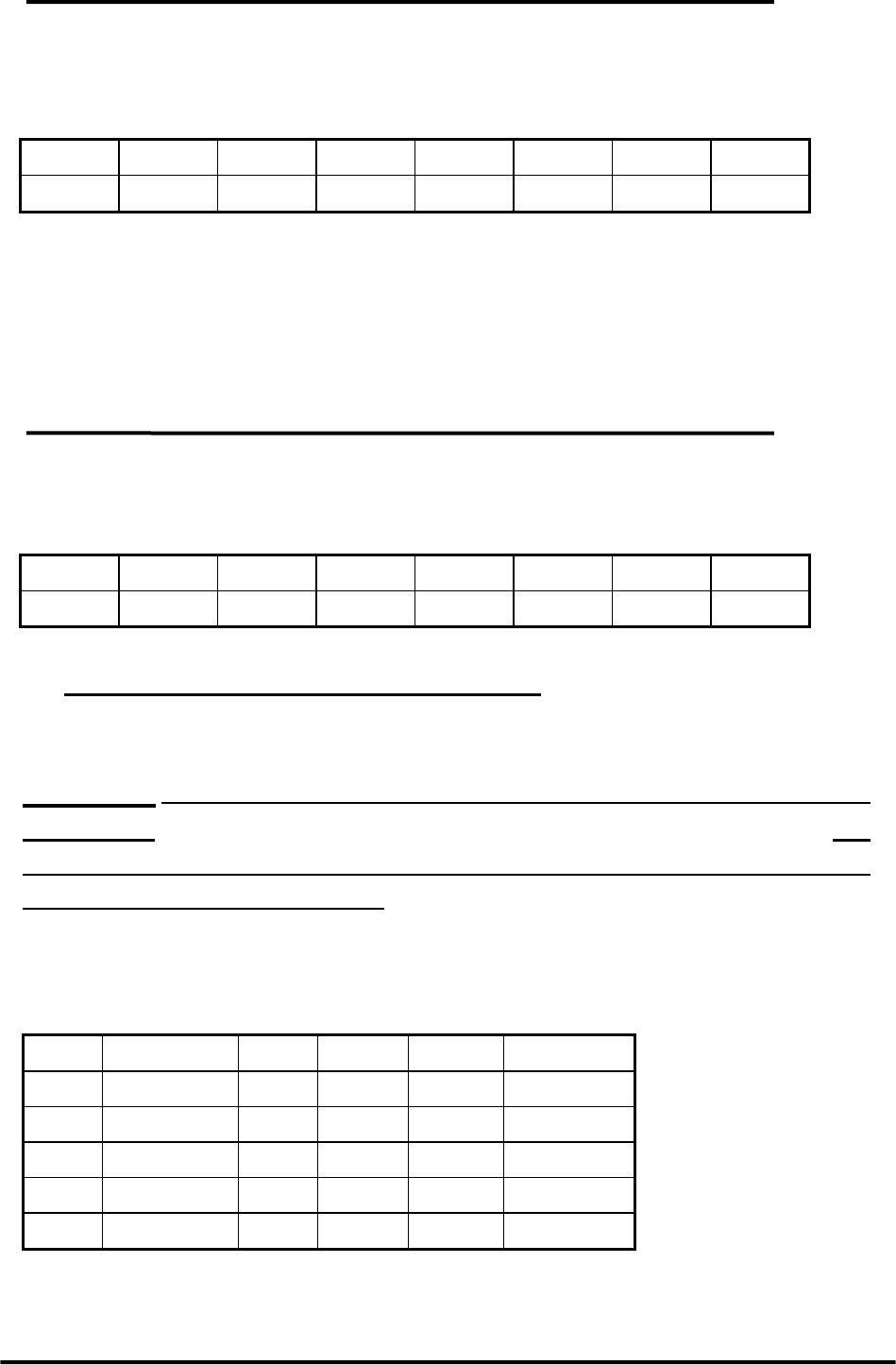
OME-A-8111 GAIN CONTROL CODE TABLE
GAIN Input Range GAIN2 GAIN1 GAIN0 Settling Time
1 +/- 5V 0 0 0 2.1 µs
2 +/- 2.5V 0 0 1 2.5 µs
4 +/- 1.25V 0 1 0 2.7 µs
8 +/- 0.0625V 0 1 1 3.6 µs
16 +/- 0.03125V 1 0 0 4.1 µs
OME-A-8111 Hardware Manual (ver.1.1, Jul/2003) 14