


14
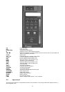
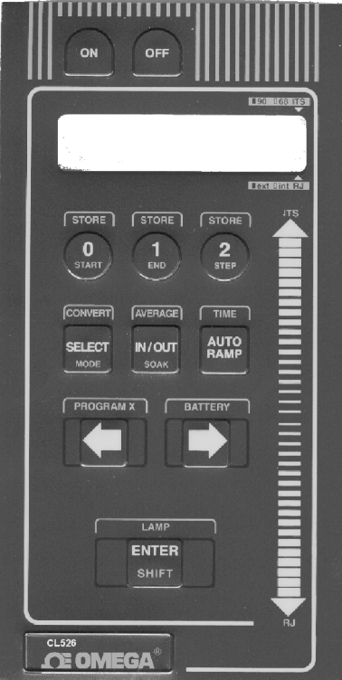
ON
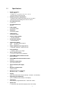
Power ON switch
OFF
Power OFF switch
IPTS68-ITS90
Temperature Scale selection
Rj
Reference junction internal-external selection
<▲
▲▲
▲> <▼
▼▼
▼> Membrane slidewires to set the simulation value (to scroll the menu of input tables and
library of engineering characters).
STORE
Memory load
<
←
←←
←
> <
→
→→
→
>
Parameter selection or decimal point position
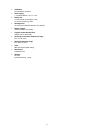
START
Low limit setting of the simulation cycle
END
High limit setting of the simulation cycle
STEP
Step value setting of the simulation cycle
MODE
Simulation cycle mode selection
SOAK
Soak time setting of the simulation cycle
TIME
Total time setting of the simulation cycle
0, 1, 2
In/Out memories
°C/°F
Technical unit selection
SELECT
Parameter selection procedure
AVERAGE
Average measurements
IN/OUT
In/Out mode selection
CONVERT
Technical unit to equivalent electrical signal
AUTORAMP
Ramp program start
PROGRAM X
Scale factor program
BATTERY
Battery voltage indication
ENTER
Memory load key
SHIFT
Key secondary function
LAMP
Display backlight switch (special - only on request)
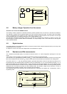
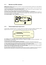
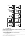
4.3 Input circuit
The input circuit is based on an output buffer wired as an error amplifier. The input signal drives the negative channel ( - )
of the integrated circuit.