


35
10 DIGITAL INTERFACE
The
CL526
portable calibrator is equipped with a digital interface. The interface circuit is essentially based on the serial
communication interface subsystem (SCI) on the chip of the microprocessor. The output voltage levels are TTL at 0 to +5
V.
An optional adaptor to convert the voltage level from 0 to +5V to RS232 levels can be supplied on request. This adaptor
is required to interface the CL526 with a Personal Computer.
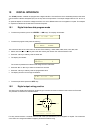
10.1 Digital interface data program mode
• To enter the procedure, press the
<ENTER>
+
<ON>
keys. The display will indicate:
CAL?
65388
N
=
0
• To enter the program mode press the
<2>
key;
B
au
d
R
a
t
e
19200
The numerical value of the “baud rate” can be one of the following : 19200, 9600, 4800, 2400, 1200, 600, 300
• Select, with the
<
▲
▲▲
▲
>
or
<
▼
▼▼
▼
>
key the “baud rate” used by the receiver unit and transmission lines.
• Press the
<2>
key to memory load the baud rate.
• The display will indicate:
ID
-
N
ame :
1
The number represents the address code assigned to the instrument.
• Press the <▲> or <▼> key to select a number from 00 to 99.
• Press the
<2>
key to memory load the programmed value.
• The display will return to the original indication:
CAL?
65388
N
=
0
• To exit the procedure press the
<OFF>
key.
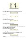
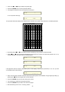
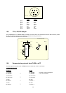
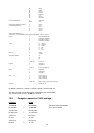
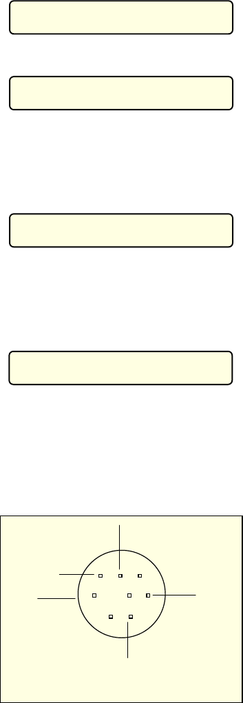
10.2 Digital output wiring practice
The wiring to the digital output signals is made through a mini DIN connector mounted on the lower end of the case.
The pertinent connections are indicated below.
ground
5 V
Tx
Rx
Female miniDIN connector
(case mounted - external view)
ground
For easy interconnections a miniDIN connector with cable (cat. EE420123) con be supplied on request. The conductors
color codes can change with different supplier; please check before using.