


4
TABLE OF CONTENTS
1 GENERAL PERFORMANCE ............................................................................................................... 6
1.1 Specifications ...................................................................................................................................................7
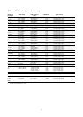
1.2.1 Table of ranges and accuracy.....................................................................................................................9
2 GENERAL FEATURES ......................................................................................................................10
2.1 Input and output flexibility...............................................................................................................................10
2.2 Self calibration................................................................................................................................................10
2.3 Keyboard........................................................................................................................................................10
2.4 Display............................................................................................................................................................10
2.5 Digital interface...............................................................................................................................................10
2.6 Scale factor function.......................................................................................................................................10
2.7 Square root function.......................................................................................................................................10
2.8 Average measurements .................................................................................................................................10
2.9 Simulation programs.......................................................................................................................................10
2.10 Case ..........................................................................................................................................................11
3 PHYSICAL DESCRIPTION ................................................................................................................ 12
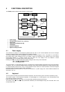
4 FUNCTIONAL DESCRIPTION........................................................................................................... 13
4.1 Power supply..................................................................................................................................................13
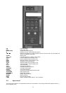
4.2 Keyboard........................................................................................................................................................13
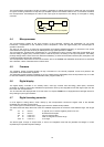
4.3 Input circuit.....................................................................................................................................................14
4.4 Microprocessor...............................................................................................................................................15
4.5 Firmware ........................................................................................................................................................15
4.6 Digital display .................................................................................................................................................15
4.7 Digital to analog converter..............................................................................................................................15
4.8 Battery charger. Operation from line source...................................................................................................16
4.9 Digital interface...............................................................................................................................................16
4.10 Resistance and Rtd measurements...........................................................................................................16
4.11 Resistance and Rtd simulation ..................................................................................................................17
4.12 Thermocouples input-output circuit............................................................................................................17
5 UNPACKING ......................................................................................................................................18
6 PRE-OPERATIONAL CHECK ...........................................................................................................19
7 ELECTRICAL CONNECTIONS..........................................................................................................20
7.1 Wiring practice...............................................................................................................................................20
7.2 Thermocouple wires .......................................................................................................................................21
8 POWER SUPPLY ............................................................................................................................... 23
8.1 Rechargeable batteries ..................................................................................................................................23
8.2 Battery Charger..............................................................................................................................................23
8.3 How to maximize the battery life.....................................................................................................................23
9 OPERATION & APPLICATIONS .......................................................................................................24
9.1 Power ON.......................................................................................................................................................24
9.2 Battery voltage indication ...............................................................................................................................24
9.3 Operating mode set up...................................................................................................................................24
9.3.1 IN - OUT mode selection ...........................................................................................................................25
9.3.2 Parameter or sensor selection...................................................................................................................25
9.3.3 Tecnical unit...............................................................................................................................................26
9.3.4 Decimal point position................................................................................................................................26
9.3.5 International Temperature Scale................................................................................................................26
9.3.6 Rj mode .....................................................................................................................................................26
9.3.7 Convert function.........................................................................................................................................26
9.3.8 Average readings.......................................................................................................................................27
9.3.9 IN-OUT data memories..............................................................................................................................27
9.3.9.1 Data memory configuration........................................................................................................................27
9.3.9.2 Data memory manual recall ..................................................................................................................28
9.3.9.3 Data memory automatic scanning.........................................................................................................28
9.3.9.4 Manual step advance.................................................................................................................................29
9.3.10 Automatic simulation cycle ........................................................................................................................29
9.3.10.1 Simulation cycle selection.....................................................................................................................29
9.3.10.2 Simulation cycle....................................................................................................................................31
9.3.11 Rj compensation mode check....................................................................................................................31
9.3.12 Scale factor program .................................................................................................................................32
9.3.13 Installation parameter procedure...............................................................................................................34
9.3.13.1 Firmware version code - Serial number ................................................................................................34