


DaqBoard/500 Series User’s Manual 887293 Connections & Pinouts 2-3
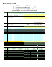
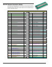
SCSI III Pinout Notes (Apply to the preceding table.)
Note 1: AOUT 1 (DAC1) applies to DaqBoard/500 only. The clock source of the secondary DAC1 channel may
be software command, DAC1 Pacer clock, or Channel 0 clock source. Likewise, the return line (ARET 1)
only applies to the DaqBoard/500.
Note 2: AOUT 0 (DAC0) applies to DaqBoard/500 only. The clock source of the primary DAC0 channel may be
software command, DAC0 Pacer clock, or an external event (DACLKIN). Likewise, the return line
(ARET 0) only applies to the DaqBoard/500.
Note 3: Pins 2 and 5 (ADCLKIN) are redundant signal connections. Only one of these pins is to be used at time.
Note 4: Pins 1 and 39 (DACLKIN/CNTR1) are redundant signal connections. Only one of these pins is to be used
at time. Use must be for either External DAC Clock In or Counter 1.
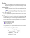
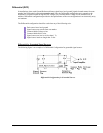
Signal Definitions
The following is a description of each of the signals available at the 68-pin SCSCI Type III connector,
as indicated in the preceding pinout.
Analog Input Channels
These channel signals are over-voltage protected to 20 V above or below the ±15 V power supply. The channel
inputs can withstand input voltages of up to ±20 volts when the power to the system is off.
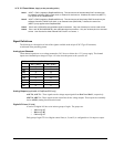
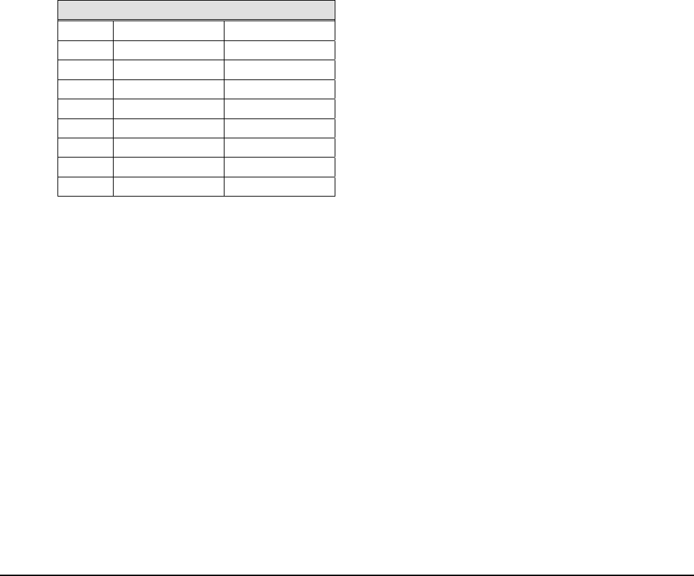
Differential Channels, Pin Reference
HI (+) Pin # LO (-) Pin #
Ch 0
68 33
Ch 1
65 30
Ch 2
28 60
Ch 3
25 57
Ch 4
34 66
Ch 5
31 63
Ch 6
61 26
Ch 7
58 23
Analog Outputs (applicable to DaqBoard/500 only)
AOUT 0, AOUT 1 - These signals are the voltage output signals from DAC0 and DAC1, respectively.
ARET 0, ARET 1 - These signals are the return lines for the voltage outputs. These inputs are essentially
tied to AGND (Analog Ground) on the board.
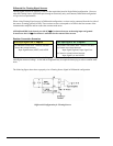
Digital I/O Lines (24 total)
A total of 24 digital I/O lines exist in three groups of eight. The groups are:
o A0 through A7
o B0 through B7
o C0 through C7
Each group of eight TTL level digital control lines (A, B, and C) is configurable as 8 bit input or output.