


DaqBoard/500 Series 988994 Software and Board Operation 4-3
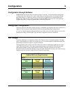
Theory of Operation
Process Definitions
In order to best understand how to operate the various board functions, it is important to first understand the
language that will be used to describe the board processes. The following is a list of pertinent terms and definitions
used in this document.
ADC
Analog to Digital Converter, also referred to as A/D. This is the circuitry that samples the voltage present at
one of the inputs and translates that reading to a number that is representative of the input voltage. The number
supplied by the ADC is referred to as the ADC DATA or RAW DATA and its units are bits or binary digits.
DAC
Digital to Analog Converter, also referred to as D/A. This is the circuitry that translates a binary data word
to a specific voltage level. The two DACs on the DaqBoard/500 are specified for DC accuracy. The DACs can be
clocked and triggered. The DAC outputs are updated as soon as they receive new data.
Note: DaqBoard/505 has no DACs.
ADC Channel
One of 16 analog input channels (see ADC).
ADC [Raw] Data
This is the unscaled number returned by the ADC. It will be in the range of 0 to +65536,
regardless of whether the data coding is for unipolar or bipolar inputs. The number is typically multiplied by a scale
factor to convert it to useful engineering units. For example: the bipolar ±10 V input uses a scale factor of
.005 V/bit. An ADC reading of +1000, when multiplied by .005 V, results in +5.000 V. Similarly, the 16-bit scale
factor for the ±10 V scale is .000130140 V/bit.
DAC [Raw] Data
This is the unscaled number sent to each DAC channel. It will be in the range of 0 to +65536,
regardless of whether the data coding is for unipolar or bipolar inputs. The number is typically multiplied by a scale
factor to convert it to useful engineering units. For example: An input in the range of 0 to 10 V uses a scale factor of
0.000152800V/bit. A DAC DATA value of 32723, when multiplied by 0.00015280, results in 5.000044 V at the
DAC output line.
ADC Conversion
This is the process of sampling a single input or transducer’s voltage and generating a
representative data value.
DAC Conversion
This is the process of outputting a single voltage generated from representative data value.
ADC Acquisition
This term refers to a series of A/D conversions. This series may consist of sampling a single
channel several times or sampling several channels sequentially one or more times. An acquisition has a clearly
defined Starting point and Ending point. Thus an acquisition may be STARTED and STOPPED.
DAC Acquisition
This term is used to refer to a series of D/A conversions. This series may consist of outputting
a single DAC channel several times or outputting both channels simultaneously one or more times. An acquisition
has a clearly defined Starting point and Ending point. Thus an acquisition may be STARTED and STOPPED.
ADC and DAC Clock
This is the signal or impetus that initiates an A/D or D/A conversion. To CLOCK the ADC
or DAC is to start an A/D conversion. The term clock is used for this process because typically a clock signal
consists of a series of pulses that are periodic or evenly timed. If the conversions are evenly spaced it is then
possible to digitally reconstruct the input waveform without distorting its component frequencies.
ADC and DAC PACER Clock
This is a timed periodic signal that may either directly clock the ADC/DAC or
initiate a burst of ADC conversions. Thus the PACER clock is exclusive to both the ADC and DAC channels.