


DaqBoard/500 Series 988994 Software and Board Operation 4-7
Clocking the DAC DaqBoard/500 Only DaqBoard/500 Only
The DaqBoard/500 includes two DAC channels.
The clock source of the primary DAC0 channel may be any of the following:
o DAC0 Pacer Clock
o External Event (DACLKIN).
The clock source for the secondary DAC1 channel is limited to the following sources:
o DAC1 Pacer Clock
o Channel 0 Clock Source.
DAC Software Update
A single D/A conversion may be initiated by an asynchronous software update. The DAC will output the data
sample for the selected DAC channel.
DAC Pacer Clocking
A series of DAC conversions may be controlled by the on-board pacer clock. This timer may be programmed to
generate a periodic clock rate as high as 100 kHz or as slow as 4 samples per hour.
DAC External Event Clocking
Conversions may also be caused by an external event. DACLKIN is an edge sensitive input that can be programmed
to cause conversions. The DACLKIN is selectable as either rising or falling edge sensitive.
DAC Maximum Clock Rate
The maximum rate which the DAC should be clocked and retain optimal accuracy is limited by the DAC chip itself.
These limits may not be exceeded. If the pacer clock is run faster, some of the clock pulses will be ignored by the
circuitry, and the clock error flag will set.
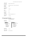
Digital Acquisition
The boards support 24 bits of LSTTL compatible digital I/O. All ports are terminated to +5 V with 4.7 KΩ pull-up
resistors. The digital I/O ports operate with positive logic, in other words “0” represents TTL Low and “1”
represents TTL High.
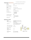
Digital Input/Output -- Ports A, B, and C
The 24 digital I/O signals from three 8-bit ports [A, B, and C] are available at the main 68-pin I/O connector. The
port channel groupings are:
o A0 through A7
o B0 through B7
o C0 through C7
For pin identities refer to the pinout in chapter 2.
Each of the three ports can be individually programmed as either an input or output.