


4-4 Software and Board Operation
988994 DaqBoard/500 Series
ADC and DAC Trigger This is the signal or impetus that initiates or terminates an Acquisition. Essentially the
Trigger Starts or Stops the ADC or DAC PACER Clock.
ADC Channel Configuration RAM
This is the term used for the ADC’s Channel, Gain, Range, and Input
Configuration lookup table. The length of this table can be anywhere from 1 element to 176 elements. When an
ACQUISITION is in process, the board will sequentially go through this list to determine the channel and gain
setting for the next conversion. Thus, channels may be sampled in any order and at any gain. Note, however, that for
maximum performance, it is recommended that channels with like gains be grouped together in the sample
sequence.
ADC and DAC DMA
Short for Direct Memory Access, DMA is the most self-sufficient of the Acquisition
Modes available over the PCI bus. In this mode, data from each conversion is automatically transferred directly
from the board to [or from] a pre-specified block of system memory. DMA allows the acquisition process to run in
the background with virtually no software overhead.
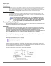
Clocking the ADC
The source of the ADC clock can be a Pacer Clock or an External Event (ADCLKIN).
ADC Pacer Clocking
A series of A/D conversions may be controlled by the on-board pacer clock. This timer can be programmed to
generate a periodic clock rate up to the ADC’s maximum rate or as slow as 4 samples per hour.
ADC External Event Clocking
Conversions may also be caused by an external event. ADCLKIN is an edge sensitive input that can be programmed
to cause conversions. The ADCLKIN is selectable as either rising or falling edge sensitive. Once an ADC clock is
received, the Analog input is immediately sampled. Converted data will become available within 5 microseconds
(max). Any attempt to clock the ADC while an A/D conversion is currently running will result in a Clock Error.
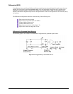
ADC Maximum Clock Rate
The maximum rate which the ADC should be clocked and retain optimal accuracy will vary depending on several
factors. These include ADC resolution (16-bits), gain setting, and sampling mode.
DaqBoard/500 Series boards use16-bit ADC chips. The chips sample at rates up to 200 kilo-samples per second.
These limits may not be exceeded. If the sample clock runs faster some of the clock pulses will be ignored by the
circuitry, and a clock error will be generated.
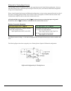
The second factor involves the front-end circuitry. The bandwidth of the front-end will vary depending on the gain
setting (and the required resolution). The bandwidth will limit the maximum signal frequency the board can pass.
Essentially, when sampling a single channel repeatedly, the ADC may be operated up to its maximum speed, but the
front-end will filter out any frequency components of the input signal that exceeds the bandwidth of the system.
When changing channels [even if the input signal is static] the front-end is required to respond to a changing input
each time the channel is changed. The net effect is that the maximum sampling speed of the ADC is limited to the
bandwidth of the front-end when changing channels.
Each time a conversion is initiated, the ADC goes into hold mode and the front-end begins to settle on the next
channel.