


7
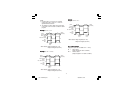
I
N
S
T
R
U
M
E
N
T
12
13
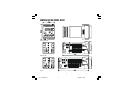
COMMON
11
M
A
S
T
E
R
12
13
11
I
N
S
T
R
U
M
E
N
T
B'/B
B/B'
A/A'
A'/A
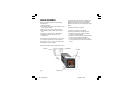
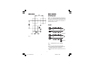
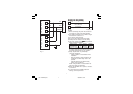
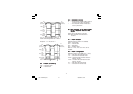
E) Power Line and groundingE) Power Line and grounding
E) Power Line and groundingE) Power Line and grounding
E) Power Line and grounding
Fig.12
NOTES:
1) Before connecting the power line, check that
the voltage is correct (see Model Number).
2) For supply connections use 16 AWG or larger
wires rated for at least 75 °C.
3) Use copper conductors only.
4) Do not run input wires with power cables.
5) Polarity does not matter for 24 Vdc wiring.
6) The power supply input is
NOT NOT
NOT NOT
NOT fuse protected.
Please provide it externally.
Power supply Type Current Voltage
24 V AC/DC T 500 mA 250 V
100/240 V AC T 125 mA 250 V
When fuse is damaged, it is advisable to verify
the power supply circuit, so that it is necessary to
send back the instrument to your supplier.
7) Safety requirements for permanently
connected equipment:
- Include a switch or circuit-breaker in the
installation.
- Place the switch in close proximity to the
equipment and within easy reach of the
operator.
- Mark the switch as the disconnecting
device for the equipment.
NOTE:
A single switch or circuit-breaker can
drive more than one instrument.
8) When the NEUTRAL line is present, connect it
to terminal 4.
9) To avoid shock and possible instrument
damage, connect power last.
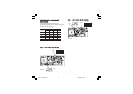
4
5
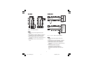
POWER SUPPLY
100 to 240 Vac
24 Vac/Vdc
N, L2
R (S,T), L1
N, L2
R (S,T), L1
Fig.11
LHL-1-NEUTRO.pmd 19/04/2004, 15.077