


9
CONFIGURATION PROCEDURECONFIGURATION PROCEDURE
CONFIGURATION PROCEDURECONFIGURATION PROCEDURE
CONFIGURATION PROCEDURE
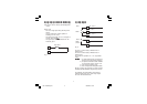
CONFIGURATION KEY FUNCTIONSCONFIGURATION KEY FUNCTIONS
CONFIGURATION KEY FUNCTIONSCONFIGURATION KEY FUNCTIONS
CONFIGURATION KEY FUNCTIONS
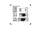
RESET In Configuration Mode, it is used only to scroll
back parameters without to memorize a new
parameter value.
Used in Configuration Mode to decrease the
parameter value.
Used in Configuration Mode to increase the
parameter value.
FUNC Used to memorize the new parameter
value and go to the next parameter.
+ Loads the default parameters.
+ FUNC or + FUNC
Increases/decreases values at a higher rate
when modifying parameters.
+ RESET or + RESET
Jumps to the Maximum or Minimum param-
eter value when modifying parameters.
CONFIGURATION PROCEDURECONFIGURATION PROCEDURE
CONFIGURATION PROCEDURECONFIGURATION PROCEDURE
CONFIGURATION PROCEDURE
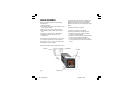
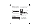
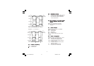
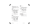
1) Remove the instrument from its case.
2) Open switch V101 (See illustrations under
“Preliminary Hardware Settings.”)
3) Re-insert the instrument in its case.
4) Switch on power to the instrument.
The upper display will show COnF.
NOTE NOTE
NOTE NOTE
NOTE : If "CAL" indication is displayed, press
immediately the V pushbutton and return to
the configuration procedure.
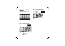
5) Press the “
” key and the lower display will
show the firmware version.
Press the "FUNC" key to start the configuration
procedure with the first parameter (L1).
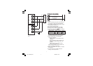
The following is a complete list of parameters. The
lower display will show the parameter code (L1 to d1)
and the upper display will show the selection code or
numerical value. No timeout is applied in the
configuration mode.
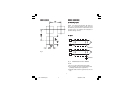
L1L1
L1L1
L1
==
==
=
Serial Interface ProtocolSerial Interface Protocol
Serial Interface ProtocolSerial Interface Protocol
Serial Interface Protocol
(Skipped if option is not available.)
OFF = No serial interface
nbUS = Modbus
jbUS = Jbus
L2L2
L2L2
L2
==
==
=
Serial Link Device AddressSerial Link Device Address
Serial Link Device AddressSerial Link Device Address
Serial Link Device Address
(Skipped if option is not available or L1 = OFF)
From 1 to 255
NOTE:
EIA standard allows no more than 31 device
connected by one RS-485.
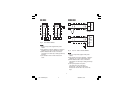
L3L3
L3L3
L3
==
==
=
Baud Rate for Serial LinkBaud Rate for Serial Link
Baud Rate for Serial LinkBaud Rate for Serial Link
Baud Rate for Serial Link
(Skipped if option is not available or L1 = OFF)
Set value from 600 to 19200 baud.
(19200 baud is shown on display as 1920)
L4L4
L4L4
L4
==
==
=
Byte Format for Serial LinkByte Format for Serial Link
Byte Format for Serial LinkByte Format for Serial Link
Byte Format for Serial Link
(Skipped if option is not available or L1 = OFF)
8E = 8 bits + even parity
8O = 8 bits + odd parity
8 = 8 bits without parity
LHL-1-NEUTRO.pmd 19/04/2004, 15.079