


6
LOAD
(mA)
<40 mA
<150 mA
<0.5 A
C
(µF)
0.047
0.1
0.33
R
(Ω)
100
22
47
P.
(W)
1/2
2
2
OPERATING
VOLTAGE
260 V AC
260 V AC
260 V AC
LOAD
R
C
POWER
LINE
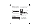
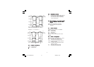
C.2) Inductive LoadsC.2) Inductive Loads
C.2) Inductive LoadsC.2) Inductive Loads
C.2) Inductive Loads
High voltage transients may occur switching
inductive loads.
Through the internal contacts these transients
may introduce disturbances which can affect the
performance of the instrument.
For all the outputs, the internal protection
(varistor) assures a correct protection up to 0.5 A
of inductive component.
The same problem may occurs when a switch is
used in series with the internal contacts as shown
in Fig. 9.
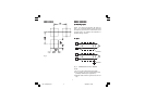
Fig. 9 EXTERNAL SWITCH IN SERIES WITH
THE INTERNAL CONTACT
In this case it is recommended to install an
additional RC network across the external contact
as show in Fig. 9
The value of capacitor (C) and resistor (R) are
shown in the following table.
The cable involved in relay output wiring must be
as far away as possible from input or communica-
tion cables.
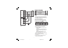
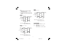
D) Serial InterfaceD) Serial Interface
D) Serial InterfaceD) Serial Interface
D) Serial Interface
For units built with optional RS-485 communication
interface.
RS-485 interface allows to connect up to 30
devices with one remote master unit.
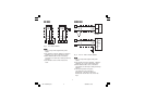
Fig. 10 - RS-485 WIRING
The cable length must not exceed 1.5 km at 9600
BAUD.
NOTESNOTES
NOTESNOTES
NOTES:
1) This RS 485 serial interface is insulated.
2) The following report describes the signal sense
of the voltage appearing across the
interconnection cable as defined by EIA for
RS-485.
a) The ” A ” terminal of the generator shall be
negative with respect to the ” B ” terminal for
a binary 1 (MARK or OFF) state.
b) The ” A ” terminal of the generator shall be
positive with respect to the ” B ” terminal
for a binary 0 (SPACE or ON).
12
13
COMMON
11
B'/B
B/B'
A/A'
A'/A
M
A
S
T
E
R
I
N
S
T
R
U
M
E
N
T
LHL-1-NEUTRO.pmd 19/04/2004, 15.076