17
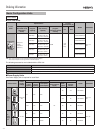
System Configuration
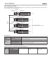
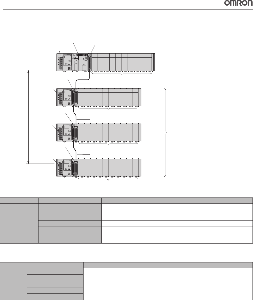
CJ-series Expansion Racks ■
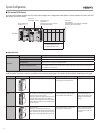
A CJ-series Expansion Rack consists of a Power Supply Unit, an I/O Interface Unit, Configuration Units (Basic I/O Units, Special I/O
Units, and CPU Bus Units), and an End Cover.
Configuration Units: 10 max.
Power Supply Unit
CJ1W-P@@@(@)
CPU Unit
CJ2H-CPU@@-EIIP
I/O Control Unit
CJ1W-IC101
I/O Interface Unit
CJ1W-II101
Power Supply Unit
CJ1W-P@@@(@)
Power Supply Unit
CJ1W-P@@@(@)
Power Supply Unit
CJ1W-P@@@(@)
CPU Rack
Expansion
Rack
Expansion
Rack
Number of Expansion Racks:
Up to 3 Expansion Racks can be connected.
I/O Connecting Cable
CS1W-CN@@3
Configuration Units: 10 max.
I/O Interface Unit
CJ1W-II101
I/O Interface Unit
CJ1W-II101
I/O Connecting Cable
CS1W-CN@@3
I/O Connecting Cable
CS1W-CN@@3
Expansion
Rack
Total
cable
length
≤ 12 m
Configuration Units: 10 max.
Configuration Units: 10 max.
Required Units ●
Rack Unit name Required number of Units
CPU Rack I/O Control Unit
One Unit. Required only when an Expansion Rack is used. Mount the I/O Control Unit immediately to the
right of the CPU Unit. (See note 1.)
Expansion
Rack
Power Supply Unit
One Unit
I/O Interface Unit
One Unit. Mount the I/O Interface Unit immediately to the right of the Power Supply Unit. (See note 2.)
Number of Configuration Units
Ten Units max. (The number of Basic I/O Units, Special I/O Units, and CPU Bus Units can be varied.
This number does not include the I/O Interface Unit.)
End Cover
One (Included with the I/O Interface Unit.)
Note: 1. Mounting the I/O Control Unit in any other location may cause faulty operation.
2. Mounting the I/O Interface Unit in any other location may cause faulty operation.
Maximum Number of Configuration Units That Can Be Mounted ●
CPU Unit Model Total Units No. of Units on CPU Rack No. of Expansion Racks
CJ2H CJ2H-CPU68-EIP
40 10 per Rack 3 Racks x 10 Units
CJ2H-CPU67-EIP
CJ2H-CPU66-EIP
CJ2H-CPU65-EIP
CJ2H-CPU64-EIP


