


Klinkmann Automation Omron Ethernet DAServer 14
Omron Ethernet DAServer Ver 1.x User Manual Rev 1.4 17014m14
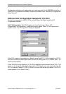
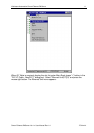
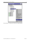
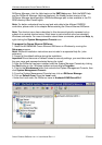
To complete the configuration: from the "Ethernet Unit CPU Bus Unit" (or from the "PLC
IO Table - NewPLC1") dialog box select "Options" and click "Transfer to PLC".
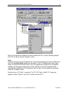
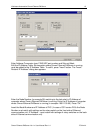
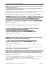
Example program for sending “unsolicited” data from PLC
The PLC example program presented in Plcprg.cxp project incorporates the SEND(090)
instruction for transferring unsolicited data from PLC to the OMRON ETHERNET
DAServer (for programming details see SYSMAC CS1 Series CS1W-ETN01 Ethernet
Unit OPERATION MANUAL, section 5).
The program transfers 10 words of data from D10 (notation in ladder diagram - D00010)
from the PLC to the OMRON ETHERNET Server (into address D500). The computer
where Omron Ethernet DAServer is running has the IP Address: 195.2.103.55 and the
destination node number is assigned to 55 (37 in hex).
Comments on example program ladder diagram:
(0) Periodically (once per second) the execution condition flag CIO 000000 turns ON.
Note: There can be different logic to turn ON execution condition flag in real
application.
(1) If the Communication Port Enabled Flag for port 7 is ON, the send execution program
will start when the execution condition flag CIO 000000 turns ON. Input CIO 120000
remains ON from the start of SEND execution until completion. Note: The CS1-series
CPU Unit’s Communication Port Enabled Flags are allocated the following way - in Word
A202: Bit 0 – is associated with Port 0, Bit 1 – is associated with Port 1, … , Bit 7 – is
associated with Port 7. Bit’s status OFF - means execution enabled, ON – means
execution disabled.
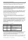
(2) Control data (D0, D1, … D4) creation
Word Contents Meaning
D0000 00 0A Number of send words = 10
D0001 00 00 Destination network number = 0 (local
network)
D0002 37 00 Destination node number = 55 (37 hex)
Destination unit address = 0
D0003 87 05 Response not required
Communication port No = 7
Number of retries = 5
D0004 00 64 Response monitor time = 10 s
Ten words with data from D10 from PLC are sent to D500 onwards on the local network,
node number 55, unit address 0 (the computer where Omron Ethernet DAServer is
running) – to receive all these data the items with addresses D500…D509 can be
correspondingly activated for Omron Ethernet DAServer.
Important! With current example program an application will periodically toggle values of
areas D500…D509 with values of areas D10…D19. This is because of DAServer time-