


30 1892 1335 - Orion Radio Modem Operating Instructions - v1.3 / Aug 2006
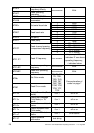
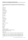
APPENDIX B: OVER-AIR COMMAND CODES
Normally the GUI is the best way to configure, control and interrogate a remote Orion unit.
However, if you want to use your own equipment and software to do this, you can use the
serial port of the local Orion to send over-air commands and receive corresponding
replies, which are listed in this Appendix.
Introduction
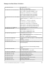
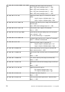
In the sections listing the various commands the following abbreviations etc are used:
Pulse Count Input = 2 byte value which is state of counter from last poll or power-on
Analogue input = 10 bit ADC value sent as 2 bytes
Analogue output = 10 bit ADC value sent as 2 bytes
IDS = ID bytes (1 digit ID number) of source
IDD = ID bytes (1 digit ID number) of destination
Note that base station will always be ID = 0
CH = CHECKSUM additive sum of bytes in message where CH is the
low order byte of the sum of all the bytes in the message, apart
from the first three. i.e. for an 04 IDS IDH 20 message, CH = the
sum of 20.
nn = 1 byte data
mmmm = 2 byte data
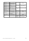
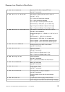
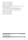
After a set command is sent, the unit will reply with a confirmation message. All I/O config
will be stored in EEPROM until an AT&W command is issued (serial port) or store config
over-air message (04 IDS IDD 27 CH) is received, when it will transfer it to non-volatile
storage.