


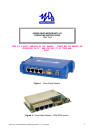

1892 1335 - Orion Radio Modem Operating Instructions - v1.3 / Aug 2006 7
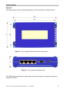
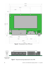
Connections
Power
Front panel, locking power plug, 2 pole with 2.1mm centre pin.
Centre conductor: +9 to +15V DC
Outer conductor: 0V (connected to unit ground)
Antenna
Female BNC, 50O
Antenna connection for both transmit and receive. The antenna will typically be mounted
directly onto this connector; otherwise the connection to the antenna should be as short
as possible and made in high-quality low-loss coaxial cable.
v Caution: do not power the Orion without an antenna or dummy load
connected, or the unit may be damaged.
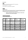
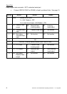
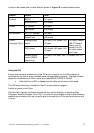
Telemetry Ports (when fitted)
Four RJ45 8-way female connectors:
RJ45
Pin No.
Port 1
Digital In
Port 2
Digital Out
Port 3
Analogue In
Port 4
Analogue Out
1 0V Relay NC 0V 0V
2 Digital input 1 Relay Common Analogue input 1 Analogue output 1
or RSSI output
3 0V Relay NO 0V 0V
4 Digital input 2 Digital output 2 Analogue input 2 Analogue output 2
5 0V 0V 0V 0V
6 Digital input 3 Digital output 3 Analogue input 3 Analogue output 3
7 0V 0V 0V 0V
8 Digital input 4 Digital output 4 Analogue input 4 Analogue output 4