


PRINTER NOTE: Page size 9” x 9.25”. Align this page to top, right hand corner. Back box bleeds off
top and right edge. Left side of page extends to 9.25 inches.
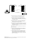
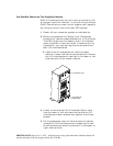
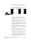
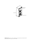
8 Connect one end of a 3 meter data cable to the
Channel #1 connector on the RAID Controller.
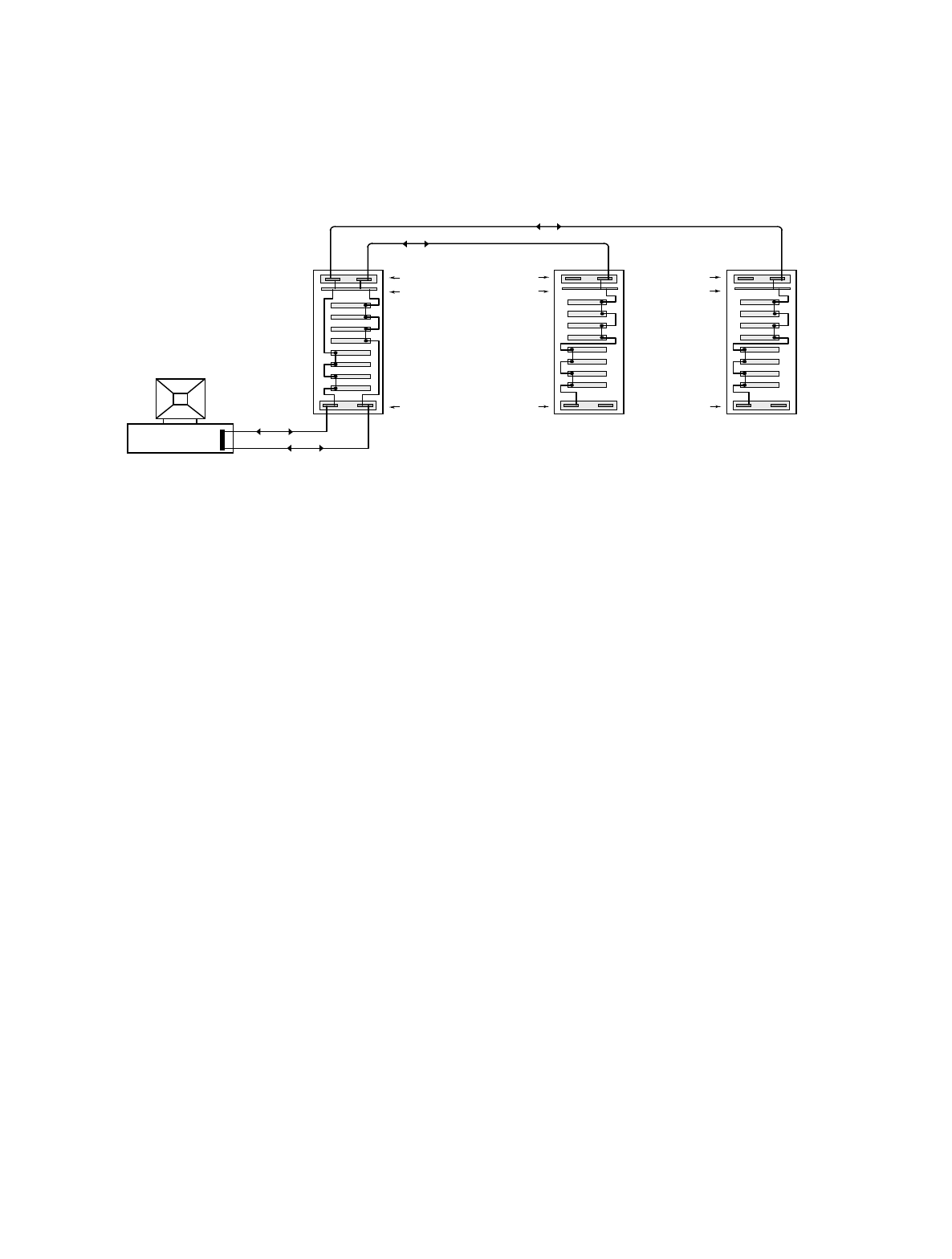
2-CH Ultra
Extender Card
TOP Master TOP Slave #1 TOP Slave #2
Host Computer #1
Dual-Bus Module
Ultra Wide SCSI
Controller
SAF-TE Card
Single-Bus Module
Single-Bus Module
SAF-TE Card
SAF-TE Card
I/O Inter-
face Card
I/O Inter-
face Card
1-CH Ultra
Extender Card
1-CH Ultra
Extender Card
I/O Inter-
face Card
1 meter Ultra Wide SCSI Jumper
1 meter Ultra Wide SCSI Jumper
Ultra Wide SCSI
Data Cable (3 meters)
Ultra Wide SCSI
Data Cable (3 meters)
Chl #1
Chl #2
Chl #0
Chl #1
Chl #0 Chl #1
Chl #0 Chl #1
Chl #0 Chl #1
Chl #0 Chl #1
Chl #0 Chl #1
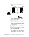
9 Connect the other end of the data cable to the
Channel 0 connector on the lower or left side two-
channel Ultra Extender Option card installed in the
master cabinet.
10 Connect one end of a 1 meter jumper cable to the
Channel 0 connector on the upper or right side I/O
Interface card in the master cabinet.
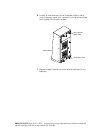
11 Connect the other end of the 1 meter jumper cable to
the Channel 1 connector on the upper or right side
single-channel Ultra Extender Option card installed
in the slaveÊ#1 cabinet.
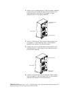
12 Connect one end of the second 3 meter data cable to
the Channel #2 connector on the RAID Controller (or
the Channel #1 connector of a second single channel
RAID Controller).
13 Connect the other end of the data cable to the
Channel 1 connector on the lower or left side two-
channel Ultra Extender Option card.
14 Connect one end of a second 1 meter jumper cable to
the Channel 1 connector on the upper or right side
I/O Interface card in the master cabinet.
15 Connect the other end of the second 1 meter jumper
cable to the Channel 1 connector on the upper or
right side single-channel Ultra Extender Option card
installed in the slave #2 cabinet.