


37
Operating
Instructions
Parts and their functions
(continued)
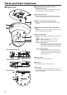
9 LAN connector for IP control [LAN ACT/LINK]
This LAN connector (RJ45) is connected when exercising
IP control over the unit from an external device.
Use a cable with the following specifications for the
connection to the LAN connector:
When connecting through a hub:
LAN cable* (category 5 or above, straight cable), max.
100 meters [328 ft]
When a hub is not used:
LAN cable* (category 5 or above, crossover cable),
max. 100 meters [328 ft]
*: Use of an STP (shielded twisted pair) cable is
recommended.
Anti-theft wire mounting hole
Use this hole to attach the wire bracket.
HDMI connector [HDMI] (AW-HE60H only)
This is the HDMI video output connector.
Hole used to secure cable cover
Use the screw provided to secure the cable cover.
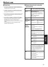
MULTI-I/F connector [MULTI-I/F]
This is the camera’s HD/SD component video signal,
composite video signal and camera’s control signal
connector.
Use the multi-interface cable purchased separately or a
cable with the DX40M-20P (made by Hirose) connector
specifications as the connecting cable.
1A10A
1B10B
p The above figure
shows the pin
layout of the
connector on the
camera as seen
from the outside.
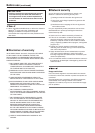
Pin
No.
Signal name
Pin
No.
Signal name
1A Y OUT 6A RX+_IN
1B Y GND 6B RX–_IN
2A Pb OUT 7A TX+_IN
2B Pb GND 7B TX–_IN
3A Pr OUT 8A GND
3B Pr GND 8B GND
4A VIDEO OUT* 9A RX+_OUT
4B VIDEO GND* 9B RX–_OUT
5A TALLY 10A TX+_OUT
5B T GND 10B TX–_OUT
*: These signals are not output
during IP video output.
DC IN connector [12V IN ]
Connect the AC adaptor supplied with the unit to this
connector to supply the DC 12 V voltage to the unit.
Cable clamp
This is used to hold the cable connection to the DC IN
connector and prevent it from becoming disconnected.
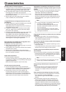
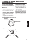
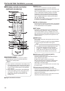
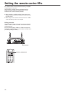
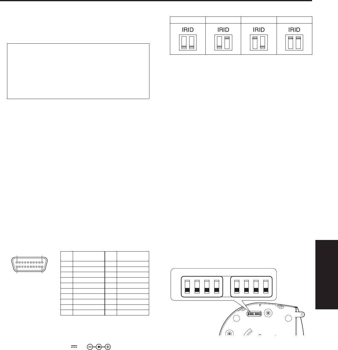
IR ID switches [IRID]
[CAM1] [CAM2] [CAM3] [CAM4]
These are used to select the ID of the wireless remote
control (optional accessory).
The IR ID switch settings “CAM1” to “CAM4” correspond
to the [CAM1] to [CAM4] buttons on the wireless remote
control.
Square holes (2) for cable cover tabs
The tabs on the two sides of the cable cover are fitted into
these holes.
SYNC IN connector [EXT SYNC IN]
(AW-HE60S only)
This is the external sync signal input connector.
This unit supports the BBS (Black Burst Sync) signal as
the external sync signal.
SDI OUT connector [HD/SD SDI OUT]
(AW-HE60S only)
This is the SDI video signal output connector.
Threaded hole (thread: 1/4-20UNC, ISO1222
[6.35 mm]) for mounting the camera
Use this hole when mounting the camera on a tripod, etc.
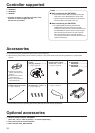
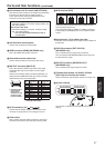
Service switches
SW1
ON
OFF
SW2 SW3 SW4 SW5 SW6 SW7 SW8
The camera is used with all the switches at the OFF
setting.