


8
7
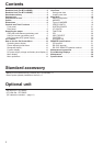
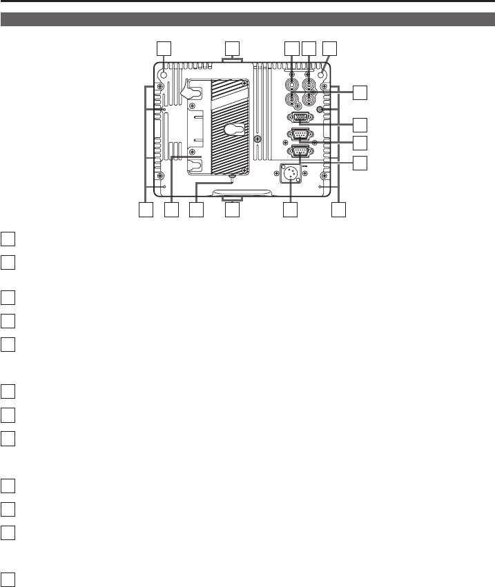
REAR TALLY (red)
Can be lit by a control signal from a GPI/camera.
8
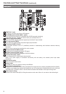
SDI (HD/SD) input terminal (BNC) - option
This is the SDI input terminal. (Compatible with HD/SD automatic switching)
• If you want this input, contact the vendor where you purchased the unit.
9
VIDEO/Y input terminal (BNC)
This is the VIDEO signal (component signal) input terminal/Y input terminal.
10
PBPR input terminal (BNC)
This is the PBPR signal (analog component signal) input terminal.
11
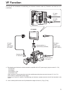
VF terminal (D-SUB, 15 pins)
This terminal connects to the VF (viewfinder) terminal of broadcasting and business cameras made by
Panasonic.
The unit can be used as the viewfinder for such a camera.
12
GPI input terminal (D-SUB, 9 pins)
External control is possible by using a GPI signal.
13
RS-232C terminal (D-SUB, 9 pins)
External control is possible by using an RS-232C interface.
14
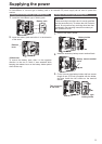
DC IN terminal (XLR, 4 pins)
This is the external DC power supply input terminal.
When a DC power supply is connected concurrently with the battery, the external power input takes
precedence.
15
Light control switch
This is not used on this monitor.
16
Battery holder
This holder is used with a battery made by Anton/Bauer.
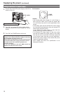
17
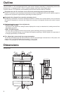
Screw holes for tripod fixing
There are two screw holes on both the top and bottom for fixing the unit to a tripod (compatible with 3/8-16UNC).
In addition, removable screw spacers are installed in one of the screw holes on the bottom of the unit, which are
compatible with 1/4-20UNC screws. Use the size that matches the diameter of the tripod’s fixing screw.
18
Screw holes for fixing
There are four screw holes (M3) for fixing the mounter on the rear of the unit, two each on the left and right.
Rear panel
Controls and Their Functions (continued)
78 97
17
14
1516
SDI
(
OPTION
)
VIDEO/
Y
P
R
VF
GPI
DC IN
RS-232C
18 18
10
11
12
13
17
PB