


9-5
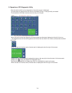
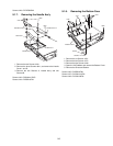
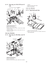
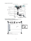
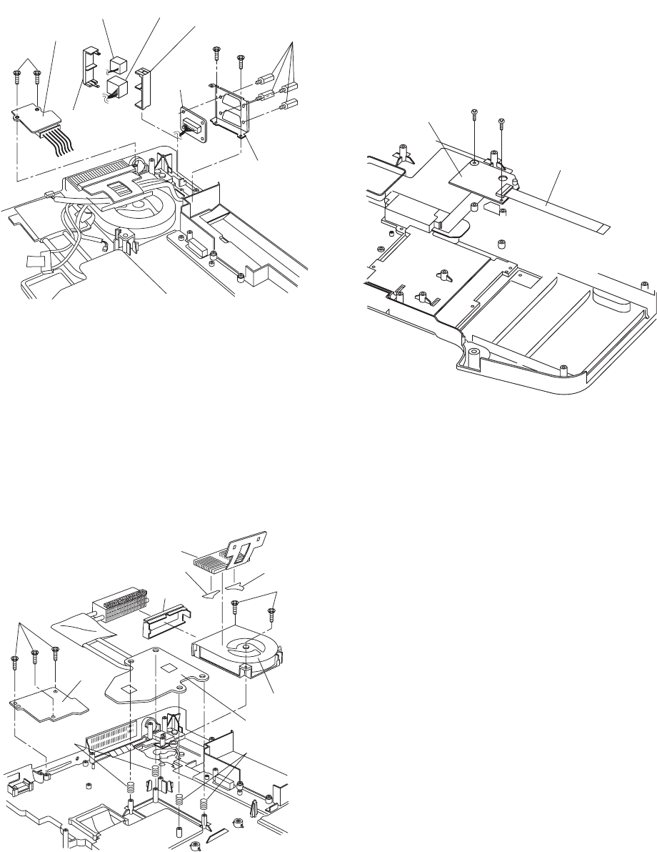
9.1.12. Removing the DC-IN PCB and I/O
PCB
1. Remove the two Screws <N9>.
2. Remove the DC-IN PCB.
3. Remove the two Screws <N9>.
4. Remove the four Screws <N19>, and then the I/O PCB
from the I/O Plate.
5. Remove the Modem Cable and LAN Cable from the
MODELAN Holders.
Screws <N9>: DFHE5025XA
Screws <N19>: DFHE5035ZB
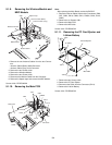
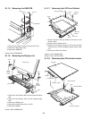
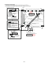
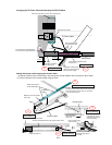
9.1.13. Removing the FAN Motor and SD
PCB
1. Remove the Cable Holder.
2. Remove the two Screws <N5>.
3. Remove the FAN Motor.
4. Remove the Heat Sink, Fan Duct, and the four Heat Sink
Springs.
5. Remove the three Screws <N9>.
6. Remove the SD PCB.
Screws <N5>: DXSB2+6FNL
Screws <N9>: DFHE5025XA
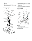
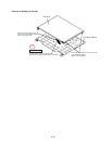
9.1.14. Removing the BT PCB
1. Remove the two Screws <N9>.
2. Remove the BT FFC from the Connector (CN2) and
remove the BT PCB.
<N9>
<N9>
DC-IN PCB
MODELAN-2
Holder
LAN Cable
MODELAN
Holder
Modem Cable
I/O Plate
I/O PCB
<N19>
<N9>
Cable Holder
<N5>
FAN Motor
Heat Sink
Fan Duct
Fan Tape1
Fan Tape2
Heat Sink
Spring
Heat Sink
Spring
<N9>
SD PCB
BT P.C.B.
<N9>
<N9>
BT FFC