


1 Introduction 4
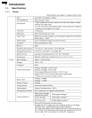
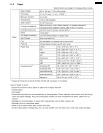
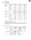
1.1. Specifications
4
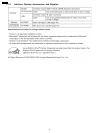
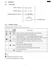
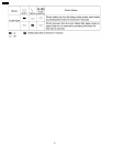
1.2. Indicators
9
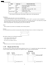
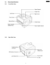
1.3. Parts Identification
11
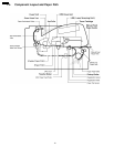
1.4. Component Layout and Paper Path
12
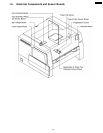
1.5. Electrical Components and Sensor Boards
13
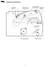
1.6. Switches and Solenoids
14
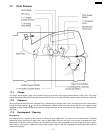
1.7. Print Process
15
1.8. Paper Feed
17
1.9. Laser Scan Unit ( Exposure )
18
1.10. Fuser Unit
20
1.11. Paper Ejection and Paper Switchback
21
2 Installation, Setup, and Repacking
22
2.1. Installation Requirements
22
2.2. Setup
22
2.3. Repacking
24
3 Removal and Replacement Procedures
27
3.1. Front and Rear Covers
27
3.2. Right, Left and Top Covers
29
3.3. Laser Scanning Unit ( LSU )
30
3.4. Relay Board (B)
30
3.5. High Voltage Board and Power Supply Unit
31
3.6. Indicator Board and Toner Empty Sensor Board
33
3.7. Main Controller Board and Fuser Drive Gear
33
3.8. Fan Motor
34
3.9. Gear Support Bracket, Motor and Drive Gear Unit
35
3.10. Upper Exit Roller Holder
37
3.11. Fuser Unit
38
3.12. Pickup, Paper Feed, Registration and Transfer Rollers
42
3.13. Transfer Roller Assembly
44
3.14. Auto Duplex Unit, ADU Registration Roller and ADU Pinch
Roller
45
3.15. Registration Sensor, Paper Top Detection Sensor and
Registration & Paper Top Detection Sensor Board
47
4 Electronic Circuit Description and Diagrams
49
4.1. Block Diagram
49
4.2. Connection Diagram
50
4.3. Power Supply
51
4.4. Main Control Board
52
4.5. Timing Chart
71
5 Schematic Diagram
73
5.1. Main Control Board
73
5.2. Sensors, Indicator and Relay Boards
79
6 Explanation of Connectors
81
6.1. Main Board
81
6.2. Registration & Paper Top Sensor Board
86
6.3. Paper Exit / ADU Paper Jam Sensor Board
86
6.4. Indicator Board
86
6.5. Relay Board ( B )
86
6.6. Toner Empty Sensor Board
87
7 Component Reference Guide
88
7.1. IC1 ( Main Control CPU )
88
7.2. IC2 ( Inverters )
88
7.3. IC3 ( GDI ASIC )
89
7.4. IC5 ( DRAM )
90
7.5. IC6 ( ASIC )
91
7.6. IC8 ( USB Chip )
92
7.7. IC9 ( Comparators )
92
7.8. IC10 ( Reset IC )
92
7.9. IC11 ( Engine Control CPU )
93
7.10. IC12 ( EEPROM )
93
7.11. IC14 ( Motor driver IC )
94
7.12. IC15 ( Inverters )
94
8 Preventative Maintenance
95
8.1. General
95
8.2. Recommended Tools
95
8.3. Recommended Cleaning
95
8.4. Maintenance Tables
95
9 Troubleshooting
98
9.1. Self-Diagnostic Indicators
98
9.2. Initial Troubleshooting Flowchart
101
9.3. No Operation
102
9.4. Print Quality
103
9.5. Paper Jam
113
9.6. Call Service
118
10 Replacement Parts List with Lubrication Guide
126
10.1. Exterior
126
10.2. Right Side Parts
128
10.3. Left Side Parts ( Power Supply Unit and High Voltage
Board )
132
10.4. Rear and Top Side Parts
133
10.5. Bottom Side Parts
136
10.6. Mechanical Base
138
10.7. Media Tray ( Paper Cassette )
139
10.8. Packing
140
10.9. Main Control Board
141
10.10. Registration & Paper Top Detection Sensor Board
147
10.11. Paper Exit / ADU Paper Jam Sensor Board
147
10.12. Indicator Board
147
10.13. Toner Empty Sensor Board
148
10.14. Relay Board (A)
148
10.15. Relay Board (B)
148
11 Schematic Diagram for printing with A4 size
149
11.1. Main Control Board
149
11.2. Sensors, Indicator and Relay Boards
162
CONTENTS
Page Page
3
KX-P7100