


About Your Projector
ENGLISH - 19
Preparation
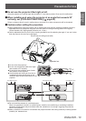
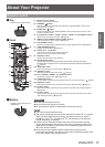
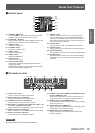
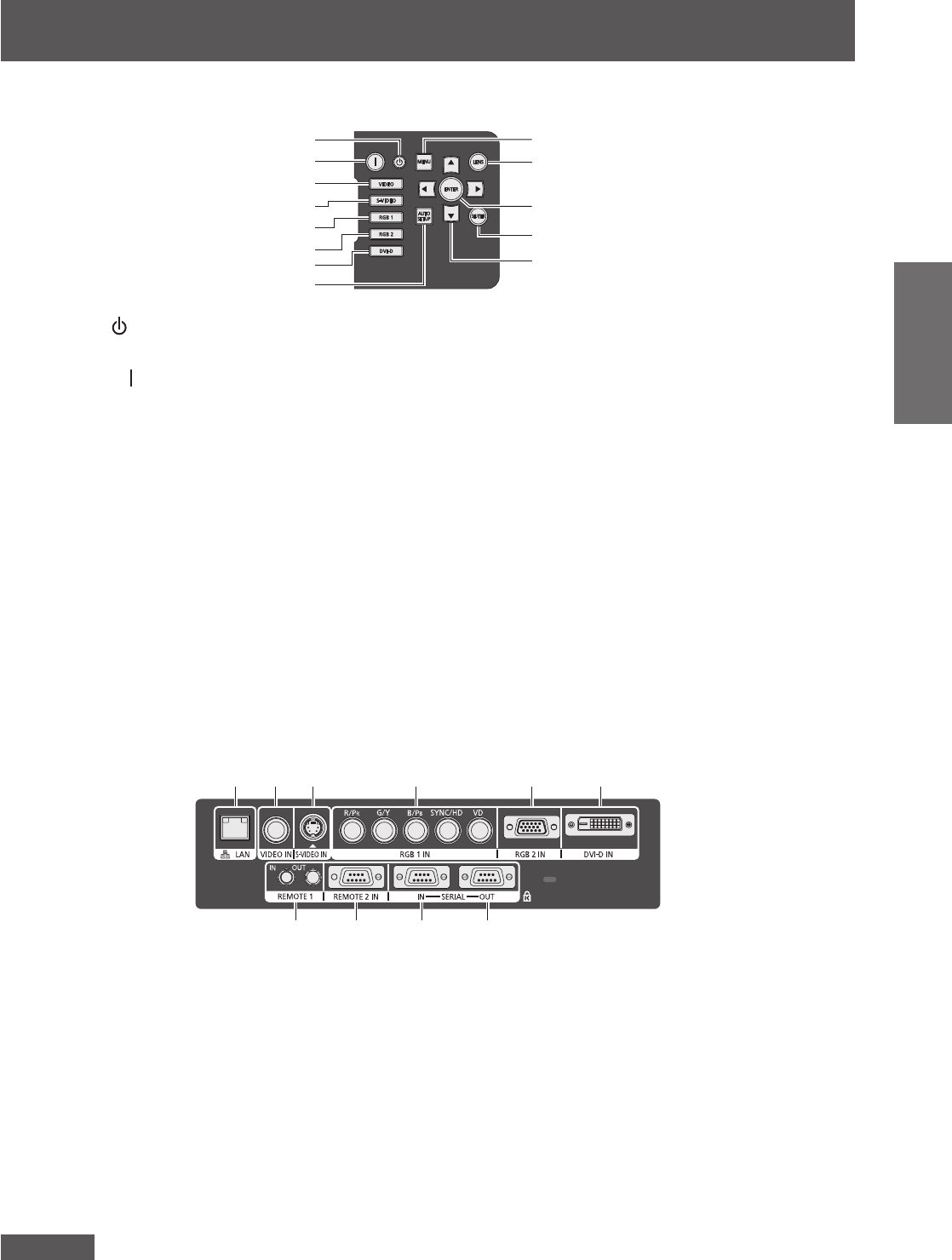
■ Control panel
(9)
(10)
(11)
(12)
(13)
(1)
(2)
(3)
(4)
(5)
(6)
(7)
(8)
(1)
STANDBY (
) button
Sets the projector to the standby mode when the <MAIN
POWER> switch on the projector is set to <ON>.
(2)
POWER ON (
) button
Starts projection when the <MAIN POWER> switch on the
projector is set to <ON> and in the standby mode.
(3) <VIDEO> button
Switches to VIDEO input.
(4) <S-VIDEO> button
Switches to S-VIDEO input.
(5) <RGB1> button
Switches to RGB1 input.
(6) <RGB2> button
Switches to RGB2 input.
(7) <DVI-D> button
Switches to DVI-D input.
(8) <AUTO SETUP> button
Automatically adjusts the image display position while
p
rojecting the image.
[
PROGRESS] is displayed on the screen while the image
is adjusted automatically. (
page 39)
(9) <MENU> button
Displays and clears the main menu, and returns to the
previous menu when the menu is displayed. (
page 41)
If you press the <MENU> button on the control panel for
at least three seconds while the on-screen indication is off,
the screen off state is canceled.
(10) <LENS> b
utton
A
djusts the focus, zoom, and shift (position) of the lens.
(11) <ENTER> button
Press to activate a menu selection or to initiate a function.
(12) <SHUTTER> button
Use this button to temporarily turn off the image. (
page 38)
(13) ▲▼◀▶ buttons
Use these buttons to select menu items, change settings,
and adjust levels. It is also used to enter the [SECURITY]
password.
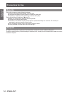
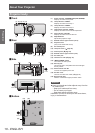
■ Terminals on side
(1) (2) (3) (4) (5) (6)
(7) (8) (9) (10)
(1) LAN terminal <LAN>
This is a terminal to connect to the network.
(2) VIDEO input terminal <VIDEO IN>
This is a terminal to input the VIDEO signal.
(3) S-VIDEO input terminal <S-VIDEO IN>
This is a terminal to input the S-VIDEO signal.
(4) RGB (YP
B
P
R
) 1 input terminals <RGB 1 IN> (<R/P
R
>, <G/
Y>, <B/P
B
>, <SYNC/HD>, and <VD>)
This is a terminal to input the RGB signal or the YP
B
P
R
signal.
(5) RGB2 input terminal <RGB 2 IN>
This is a terminal to input the RGB signal or the YP
B
P
R
signal.
(6) DVI-D input terminal <DVI-D IN>
This is a terminal to input the DVI-D signal.
(7) REMOTE 1 IN terminal <REMOTE 1 IN>/REMOTE 1 OUT
terminal <REMOTE 1 OUT>
These are the terminals to connect the remote control for
serial control when the system uses multiple projectors.
(8) REMOTE 2 IN terminal <REMOTE 2 IN>
This is a te
rminal to
remotely control the projector using the
external control circuit.
(9) SERIAL IN terminal <SERIAL IN>
This is a RS-232C compatible terminal to externally control
the projector by connecting a computer.
(10) SERIAL OUT terminal <SERIAL OUT>
This is a terminal to output the signal connected to the
SERIAL IN terminal.
Attention
z
Connect the LAN to the indoor equipment.