


-60-
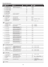
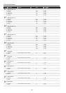
Electrical Adjustments
Group/
Item
Item Name Function Initial Range Note
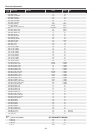
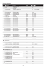
11 CR - GAIN AREA V START 500 0 - 1000
12 Image AREA H WIDTH YCBCR Level Acquiring Area 13 0 - 4095
13 Image AREA V HIGHT YCBCR Level Acquiring Area Height 9 0 - 4095
14 Y - OFFSET TARTGET 4 1 - 255
15 CB OFFSET TARGET 128 1 - 255
16 CR OFFSET TARGET 128 1 - 255
17 Y-GAIN TARGET 217 1 - 255
18 CB-GAINTARGET 237 1 - 255
19 CR-GAINTARGET 237 1 - 255
20 OFFSET torelance Torelance of OFFSET Adj. 1 1 - 255
21 GAIN torelance Torelance of GAIN Adj. 1 1 - 255
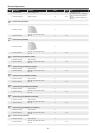
Group
270
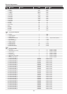
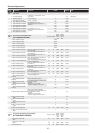
CUSTOM(Aspect)
0 Scaler Horizontal Horizontal Scaler Edit 100 68-132
1 Sclaler Vertical Vertical Scaler Edit 100 68-132
2 Connect Seperate/Connect Edit 0 0-1 0:Seperate, 1: Connect
3 Position Horizontal Horizontal Postion Correction 100 85-115
4 Position Vertical Vertical Position Correct 100 85-115
5 Aspect Enable 0 0 - 1 0: False, 1: True
Group
275
DLV Illuminance Sensor
0
Illuminance
measurements(ADC)
Illuminance measurements(ADC) - 0-255 * Read only
1 Illuminance data(Lx) Illuminance data(Lx) - 0-1023 * Read only
2 DLV_Level DLV_Level value - 0-3 * Read only
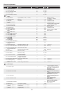
3 L1 Value(Floor)
Reference value switching Level1->
0 when (illuminance value)
36 0-255
4 L2 Value(Floor)
Reference value switching Level 0->
at the time of a value (brightness)
67 0-255
5 L3 Value(Floor)
Reference value switching Level2->
when a (illuminance value)
86 0-255
6 L4 Value(Floor)
Reference value switching Level1->
when 2 (illuminance value)
121 0-255
7 L5 Value(Floor)
Reference value switching Level3->
when 2 (illuminance value)
161 0-255
8 L6 Value(Floor)
Reference value switching Level2->
3 o'clock (illuminance value)
202 0-255
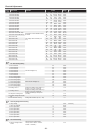
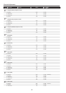
9 L1 Value(Ceiling)
Reference value switching Level1->
0 when (illuminance value)
18 0-255
10 L2 Value(Ceiling)
Reference value switching Level 0>
at the time of a value (brightness)
21 0-255
11 L3 Value(Ceiling)
Reference value switching Level2->
when a (illuminance value)
24 0-255
12 L4 Value(Ceiling)
Reference value switching Level1->
when 2 (illuminance value)
32 0-255
13 L5 Value((Ceiling)
Reference value switching Level3->
when 2 (illuminance value)
39 0-255
14 L6 Value(Ceiling)
Reference value switching Level2->
3 o'clock (illuminance value)
51 0-255
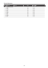
15 DLV ON_Level Level of DLL in the ON mode of DLV 3 0-3
Group
276
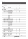
DLV Image quality correction
0
Color correction gain (PW)
To enable / disable color correction
PW gain during DLV Auto / On
1 0-255 0:Enabel, 1:Disable
1
correction gain user R
(Gamma)
To enable / disable user R gain
compensation at the time of DLV
Auto / On
1 0-255 0:Enabel, 1:Disable
2
Correction Sub Gamma
(Gamma)
To enable / disable Sub Gamma
correction when the DLV Auto / On
1 0-255 0:Enabel, 1:Disable
3
Sharpness correction (PW)
Enable / disable the correction of
sharpness when DLV Auto / On
1 0-255 0:Enabel, 1:Disable
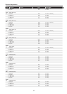
Group
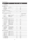
280
AutoPC Adjust
0 AutoPCAdjustEnable
Auto-PC Adj Operation Enable if Un-
supported Signal Input
0 0-1 0:Enabel, 1:Disable
1 Frequency Step Frequency Steps of Total Dot 1 0-3
2 Frequency Threshold Total Dot Freqency Threshold 5 0-10 0[]<-- - --> 10[Not matched]
3 Fine Phase Do Phase Adj after Total Dot Adj. 1 0-1 0;Excutes Fine Phase; 1:Not Excute
4 BLKDET Black Level Detection Area 1 0 - 7
5 PHASEMSK Phase Detection Filter 0 0 - 3
0: Effective All Bit,
1: Disable Lower 1 bit
2: Disable Lower 2 bit, 3: Disable
Lower 3 bit
Group
290
PanelType