


-73-
Troubleshooting
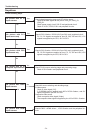
No power
- When all of LED indicators are not lighting, the symptom indicates that the primary power supply circuit does
not operate properly. Check the power primary circuit and parts as follow;
AC cord, F601 (Fuse), Power board, SW902 (Thermal fuse)
SW902 opens when the surrounding temperature of the switch exceeds 113°C.
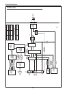
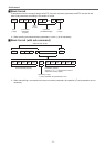
This projector provides a function which can be specified a defective area simply by indicating the LEDs. Connect the
AC cord and press the button once and then check the LED indication.
- When the WARNING (red) and ON(G)/STANDBY(R) (orange) indicators are flashing, the symptom indicates
that the projector detected an abnormal temperature risen inside the projector. Check the air filters and remove
the object near the intake and exhaust fan openings, and wait until the ON(G)/STANDBY(R) indicator stops flash-
ing, and then try to turn on the projector.
The internal temperature is monitored by sensor ICs, IC8831, IC8821 on the MAIN board and IC8811 on the R/C
board.
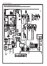
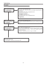
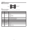
- When the WARNING indicator lights red, the symptom indicates that the projector detected an abnormality in
the cooling fan operation or in the power supply secondary circuits. Check fan operation and power supply lines,
and the driving signal status.
The P_FAIL signal (Error: L), FAN_ERR_B signal (Error: L) and FAN_FAIL1 signal (Error:L) are sent to pins, 215
and 29 of IC301 <SYSTEM CONTROL> respectively when the abnormality occurred inside the projector, and
then the IC301 sends the shutdown signal, LAMP_DC_ON, to the power supply circuit to stop its operation, and
signal LAMP_SCI to the lamp ballast board via IC9885 and SW901<lamp cover switch> to stop operation of the
lamp circuit.
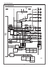
An abnormality occurs on the secondary power supply;
Check power supplies S16.5V, S6V, S-7V.5VSTB, P_FAIL signal becomes Low when the abnormality oc-
curs on any of the power supply lines.
An abnormality occurs on the fan control circuit;
If fans FN901, FN902, FN903, FN904, FN905,FN909 has an error, the FAN_ERR and P_FAIL signals
become "L". If fans FN909, FN910 has an error, the FAN_ERR_B signal become "L".
If fans FN906,FN907,FN908,FN910 has an error, the FAN_FAIL1 signals become "L".
The FAN_ERR signal cuts off the LAMP_SCI signal which is supplied to the lamp ballast board if the
FAN_ERR signal is "L".
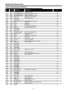
An abnormality occurs on the drive signals;
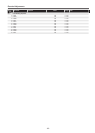
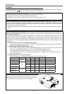
The driving signals for the each power supply are shown in the table below.
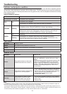
Drive signal Output IC Pin I/O Level Switch/IC Power/Circuit
15.25P_SW
IC501
42 O H IC582 15.25V
12.25A_SW 154 O H IC592 15.25V_A
POW_GAM_3.3V
IC301
276 O H IC411 3.3V
POW_GAM_2.5V 353 O H IC431 2.5V
POW_GAM_1.8V 271 O H IC441 1.8V
POW_GAM_1.0V 276 O H IC421 1.0V
POWER_SW1
IC9885
17 O H
IC5821
IC5861
S3.3V
S1.8V
POWER_SW 5 O H RL601 Standby circuit
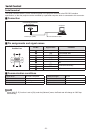
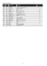
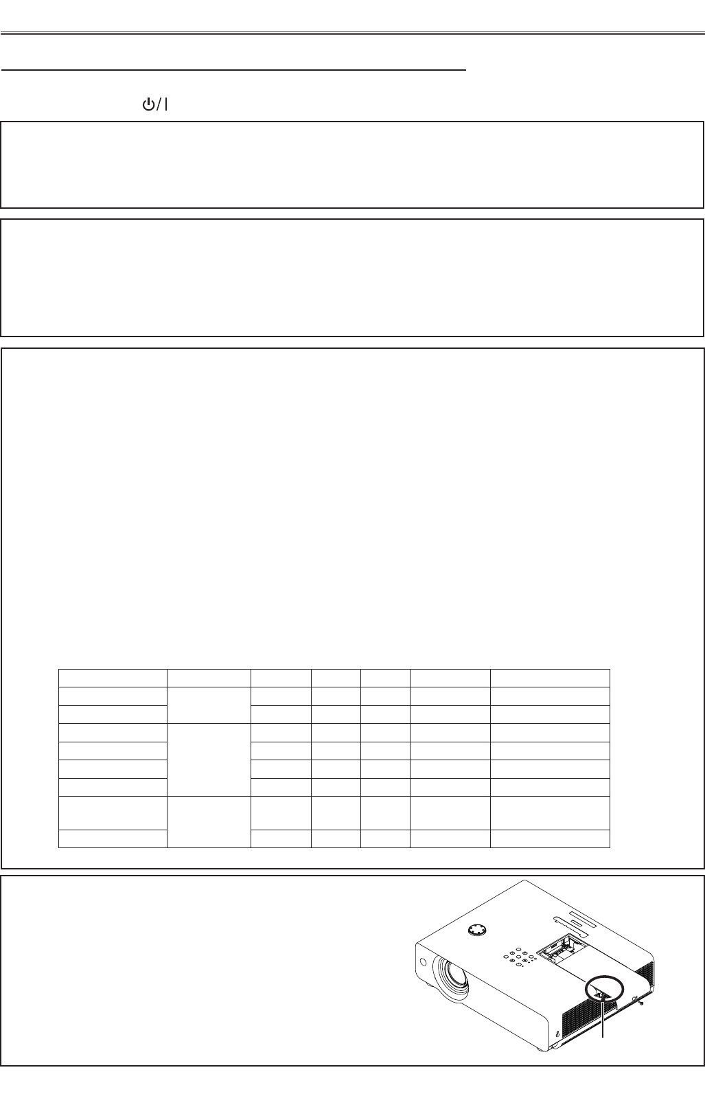
Lamp cover switch
Make sure that the lamp cover is mounted correctly. If not or the
lamp cover removed, the lamp does not light on for the safety.
Check the lamp cover and lamp cover switch (SW901).
SW901