


PANDUIT® DPoE™ Power Patch Panel User’s Guide Issue 2.2
Part Number: PN378A
56
4. Record the rack space position on the Installation
Worksheet.
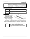
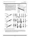
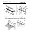
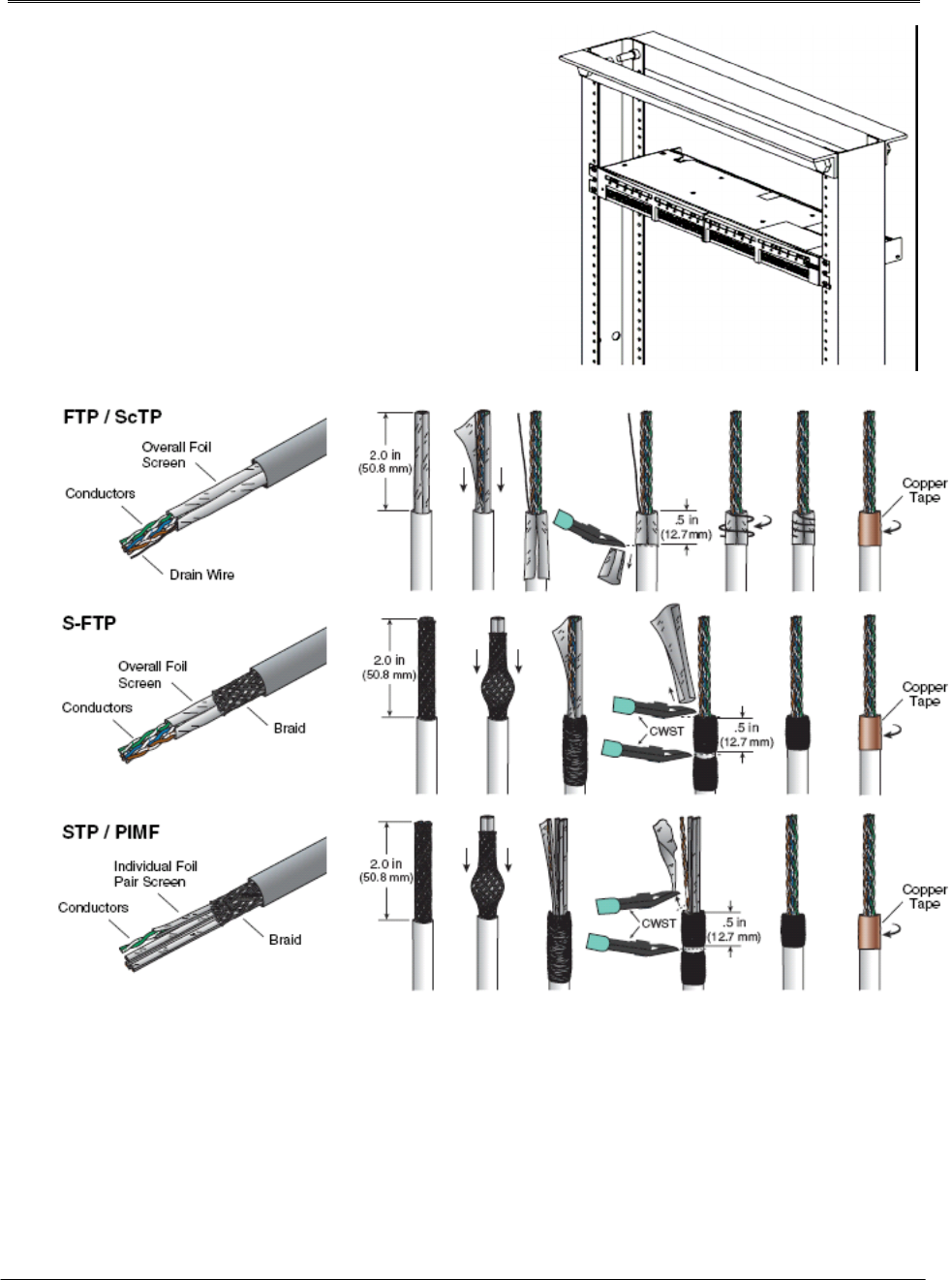
5. Prepare the shielded cables for termination using
the figures appropriate for the type of cable used.
Caution: Do not damage conductors. To ensure
the highest shielding effectiveness, cut 1.5” (38.1
mm) of copper tape, included in 4 strips inside the
Power Patch Panel Installation Kit, and wrap it
around the cable foil or braid. Refer directly to the
Installation Instructions or the diagrams below for
proper cable termination depending on the type of
shielded cable being used:
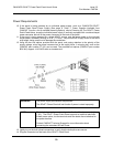
Connecting the Powered Devices
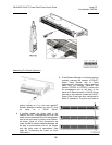
6. After the cables are properly terminated, place conductors into the punchdown slots in the
appropriate wiring sequence. In order to support pre-standard powered devices utilizing Cisco
Inline Power, the ALT POE "A" or ALT POE "B", corresponding to a EIA/TIA 568A or EIA/TIA
568B configured data pairs, wiring sequence must be used.