


PANDUIT® DPoE™ Power Patch Panel User’s Guide Issue 2.2
Part Number: PN378A
61
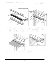
Powering Up the DPoE™ Power Patch Panel
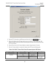
17. Apply power the panel. Once power is applied to the unit, the
DPoE™ Power Patch Panel will go
through its power up sequence. The following table describes the behavior of the unit as viewed
from the front and the back.
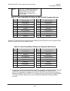
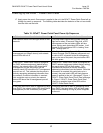
Table 19: DPoE™ Power Patch Panel Power Up Sequence
Behavior as viewed from the back of the unit Behavior as viewed from the front of the unit
Both network status LEDs will light amber for two
seconds
The panel status Light-Emitting Diode (LED) will
light red for about 10 seconds. After that, a LED
test sequence of the port status LEDs will take
place, lighting each port status LED amber. It will
appear as if the port status LED is “walking” from
port 1 through port 24.
If there is no cable connected to the IN
management port (Step 9 above), both network
status LEDs will turn ff.
If the Patch Panel is configured for Dynamic Host
Control Protocol (DHCP) address assignment and
a cable is NOT connected to the IN management
port on the rear of the panel, the panel status LED
will blink green.
If the DPoE™ Power Patch Panel is configured
for DHCP address assignment (default factory
setting), the network status LED above the IN
management port will stay amber and the
network status LED above the OUT management
port will turn off. This indicates that the panel is
actively requesting addressing information from
the network. Once this information is received
(this could take up to a minute), the network
status LED above the IN management port will
turn green.
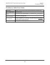
If the
DPoE™ Power Patch Panel is configured for
DHCP address assignment (default factory setting),
the panel status LED will flash amber. This
indicates that the panel is actively requesting
addressing information from the network. Once this
information is received (this could take up to a
minute), the panel status LED will flash green as
power is applied to the unit. (See page 5,
Figure 1:
DPoE™ Power Patch Panel (Front View) and page
6,
Figure 2: DPoE™ Power Patch Panel (Rear
View)
for a graphical view of the LEDs on the
DPoE™ Power Patch Panel.)
If the panel were set to static IP addressing rather
than DHCP, the network status LED above the IN
management port will immediately turn green.
If the panel were set to static IP addressing rather
than DHCP, the panel status LED will flash green
and continue flashing as long as power is applied
to the unit.