


COMSPHERE –48 Vdc Central Office Power Unit
2-2 May 1998 3000-A2-GB41-40
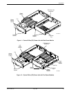
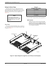
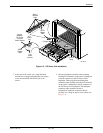
directly above the bottom carrier should have its power
module installed in the right side of its CO power tray.
Then, the next carrier directly above should have its
power module installed in the left side of its CO power
tray, and so on for the remainder of the carriers in the
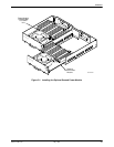
cabinet. For information on removing and installing a
power module, see the Power Module Replacement
Instructions section in Chapter 3.
With the power modules placed in alternating
sequence, the maximum operating ambient temperatures
listed in Table 2-1 are permitted.
Independent Mode of Operation
In the Independent mode of operation, the left power
module (as viewed from the front of the carrier) powers
Slots 1 through 8 of the carrier and the right power
module powers Slots 9 through 16 of the carrier. The
Shared Diagnostic Unit (SDU), contained in Slot 0, is
powered by both power modules. If a power module fails,
only the service to that side of the carrier is disrupted. The
other side of the carrier is unaffected. Do not remove a
failed power module until a replacement is available. To
replace a power module, see the Power Module
Replacement Instructions section in Chapter 3 of this
guide.
When the power modules are configured for
Independent mode of operation, up to six carriers can be
mounted in a cabinet. The maximum ambient temperature
is 50°C.
The –48 Vdc input can be provided in one of two
powering options:
• Using two separate –48 Vdc power sources and two
input power cables.
• Using one –48 Vdc power source and two input
power cables.
For maximum reliability, use the first option. For more
information on these powering options, see the Providing
Power to a CO Power Unit section.
To change the mode of operation, see the Setting the
Option Straps section.
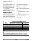
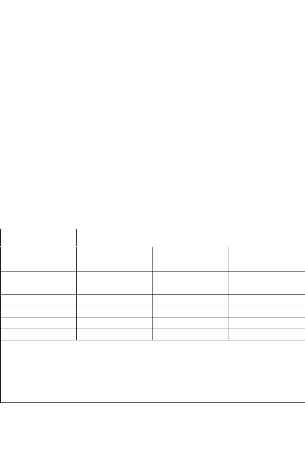
Table 2-1
Maximum Ambient Temperatures Permitted
Maximum
Allowable Number of Stacked COMSPHERE 3000 Series
Carriers in a Cabinet
Maximum
Ambient
Temperature
3551 and 3611 DSUs
without DBMs, 3511
DSUs, 3151 and CSUs
2
3551, 3611, and 3616
DSUs with DBMs and
3811 Modems
2
3161 DSU/CSUs
1
122°F (50°C)
4 2 See Note 4
113°F (45°C)
5 3 1
3
, 2
104°F (40°C)
6 4 3
ă95°F (35°C)
6 5 4
86°F (30°C)
6 5 5
77°F (25°C)
6 6 6
NOTES:
1
These operating ambient temperatures can be increased by 5°C by placing 3161 DSU/CSUs in cooler
slots (2, 3, 4, 5, 10, 11, 12, 13), or by leaving a slot empty next to each 3161 DSU/CSU.
2
Use the strictest cooling requirements when there is a mixture of units installed.
3
Requires a power module on each side, otherwise the ambient temperature must be restricted to 35°C.
4
A single carrier, equipped with two power modules, can operate at 50°C provided the cooler slots (2, 3, 4,
5, 10, 11, 12, 13) are used.